
CCP MODULE:CCP stands for Capture, Compare and PWM. These are built in module in pic microcontroller. It is a special module in pic microcontroller designed for modulation and waveform generation applications. It is also used to generate specific time delay.This module OF pic microcontroller contains a 16-bit register which can operate as:
- 16-bit Capture register
- 16-bit Compare register
- 10-bit PWM master/slave Duty Cycle register
CAPTURE MODE:
If a register constantly change its value, this mode provides access to the current state of that register. In this case, it is the timer TMR1 register.
COMPARE MODE:
This mode constantly compares values of two registers. One of that register is the timer TMR1 register. When a predetermined amount of time expires, this circuit also allows the user to trigger an external event.
PWM (PULSE WIDTH MODULATION)
This mode can generate signals of varying frequency and duty cycle on one or more output pins.
Table of Contents
CCP MODULE IN PIC18F452 microcontroller
PIC18F452 microcontroller contains built in two CCP modules (CCP1 and CCP2). Both modules are identical in there operation except inthe special event trigger operation. In this article, the CCP1 module is discussed in detail.
TIMER RESOURCES:
For the CCP module to function, Timer must be used in combination with CCP module. In each CCP module, the capture, compare and PWM modes use different timer resources. The timers resources require by them are:
- Capture Timer1
- Compare Timer1
- PWM Timer2
CCP1 MODULE of pic microcontroller
The central part of this module’s circuit contains a 16-bit CCPR1 Register which consists of:
- 8-bit CCPR1L Register (low byte)
- 8-bit CCPR1H Register (high byte)
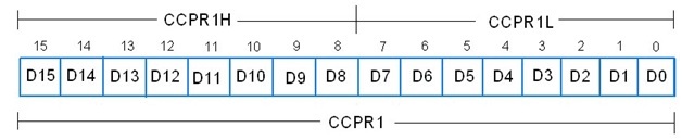
This register is used for capturing or comparing with binary numbers stored in the timer register TMR1 or we can say that count is loaded in this register to compare.
CCP1CON Register:
The modes of CCP module are selected using the bits of CCPCON Register (CCP control register) which is shown below. Its lowest bits (0, 1, 2, 3) CCPxM3: CCPxM0 are used for selection of CCP mode which is explained further in process of capture and compare modes.
0000 = Capture/Compare/PWM off (it will reset CCP module)
- CCP1 CAPTURE MODE:
In this mode, the timer register TMR1 which consists of TMR1H and TMR1L is copied to the CCPR1 register (CCPR1H and CCPR1L). The combination of the four bits (CCP1M3-CCP1M0) of the control register determines which of these events will cause 16-bit data to be transferred. It can be done as:
CCP1CON Register Bits 3:0
- 0100 Capture mode, Every falling edge on RC2/CCP1 pin
- 0101 Capture mode, Every rising edge on CCP1 pin
- 0110 Capture mode, Every 4th rising edge on CCP1 pin
- 0111 Capture mode, Every 16th rising edge on CCP1 pin
Note:
The RC2/CCP1 pin should be configured as an input pin and TMR1 module must operate as timer or synchronous counter.
- CCP1 COMPARE MODE:
In this mode, the value stored in 16-bit CCPR1 register will be constantly compared against the value stored in TMR1 OR TMR3 register. If CCPR1 Register value gets match with Timer value then the logic state of the RC2/CCP1 output pin may be changed and CCP1IF (Interrupt Flag) is generated. Which logic will generate, it willagain depend on the state of bits in the control register (CCP1M3 – CCP1M0).
CCP1CON Register Bits 3:0
- 1000 = Compare mode, Initialize CCP pin Low, on compare match force CCP pin High (CCPIF bit is set)
- 1001 = Compare mode, Initialize CCP pin High, on compare match force CCP pin Low (CCPIF bit is set)
- 1010 = Compare mode, Generate software interrupt on compare match, CCP pin is unaffected (CCPIF bit is set)
- 1011 = Compare mode, Trigger special event (CCPIF bit is set)
Note:
For this mode, the RC2/CCP1 pin must be configured as an output pin and Timer TMR1 must be synchronized with internal clock.
T3CON register is used to select Timer1 or Timer3 for compare mode.Timer3 Control Register is shown below: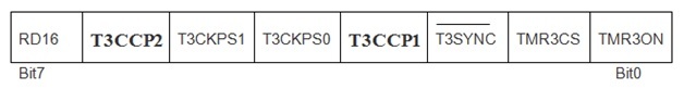
T3CCP2:T3CCP1: Used to select Timer for Compare mode operation.
- 00= Timer1 for both CCP module
- 01= Timer1 for CCP1 module
Timer3 for CCP2 module
- 1x= Timer3 for both CCP module
- CCP1 PWM MODE:
The signals which have varied frequency and duty cycle have wide range of applications in automation.Pulse width modulation (PWM) is a great technique for controlling analog circuits with microcontroller digital outputs. If the signal is high, that will indicate the on time and if it is low, that is the off time. From this we can determine the duty cycle.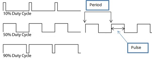
PWM PERIOD of CCP module in pic microcontroller
The output pulse period (T) of waveform is determined by the PR2 register of the timer TMR2. The PWM period can be calculated as:
PWM Period = TPWM = (PR2 +1) * 4*TOSC * TMR2 Prescale Value
- If FOSC is 20MHz
- TOSC=1/ FOSC=0.05 µs
- TMR2 prescale value=1
- If PR2=0xFFFF=65535
PWM Period= TPWM= (65535+1) *4 *0.05µs * 1 = 13.1ms
FPWM = 1/TPWM= 76KHz.
PWM DUTY CYCLE:
The PWM duty cycle is specified by using total 10 bits:
- MSBs consist of eight bits of CCPR1L register
- LSBs consist of the 2 bits of CCP1CON register (DC1B1 and DC1B0)
Firstly we have to write a 10-bit value (from 0 to 1023) to the CCPR1L register concatenated with CCP1CON<5:4> bits. The formula for calculation is:
Pulse Width = (CCPR1L,DC1B1,DC1B0) * Tosc * TMR2 Prescale Value
- Since duty cycle = value/[4*(PR2+1)]
- If program starts with 50% duty cycle
- TOSC = 0.05 µs
- TMR2 prescale value=1
duty cycle = value/[4*(PR2+1)]
value=duty cycle*[4*(PR2+1)]
value=(50/100)*[4*(65535+1) = 131072
PWM Duty Cycle = (CCPR1L:CCP1CON<5:4>)*Tosc*Timer2 prescale value
= 131072*0.05 µs *1 = 6.5ms
For getting desired PWM frequencies using Fosc = 20 MHz, the Timer Prescaler and PR2 values can be set as: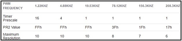
How to generate PWM using CCP module of pic microcontroller
In this example we will use the compare mode to generate a 50Hz output with 50% duty cycle. Crystal oscillator of frequency 20MHz is used with PIC18F452. Pin RC2 is used as output pin. And Oscilloscope is used to monitor the output wave.
CALCULATIONS:
- FOSC is 20 MHz
- TOSC=1/ FOSC =0.05 µs
- TMR2 prescale value=1
- If PR2=0xFFFF=65535
PWM Period= TPWM = (65535+1) * 4 * 0.05µs * 1 = 13 ms
FPWM = 1/TPWM = 76KHz.
TMR1 increment takes 1 instruction cycle (with prescaler 1:1) or we can say that TMR1 overflow takes 65536 instruction cycles. For 50Hz:
- Time period = TPWM =20ms
- Tcy = (1/20MHz)*4 = 0.2µs
- with 50% duty cycle, on time is 10ms
- The number of instruction cycles in 10ms = 10ms/0.2 µs = 50000
This means that 10ms have elapsed when TMR1 counted from 0 to 50000. So what we do next is:
- Assign CCPR1 = 50000 = 0xC350
- CCPR1H = 0xC3 and CCPR1L = 0x50
- compare match occurs every 10ms now
- TMR1 is reset upon compare match
PROGRAMMING OF CCP module
- RC2 is set as output pin.
- For our required mode of operation CCP1CON = 0x0B.
- Since CCP interrupt will be used, CCP1IE must be set. GIE and PEIE also have to be set.
- We’ll do the toggling in the interrupt service routine (ISR).
- After every 10ms, the state of RC2will be toggled.
PROTEUS SIMULATIONS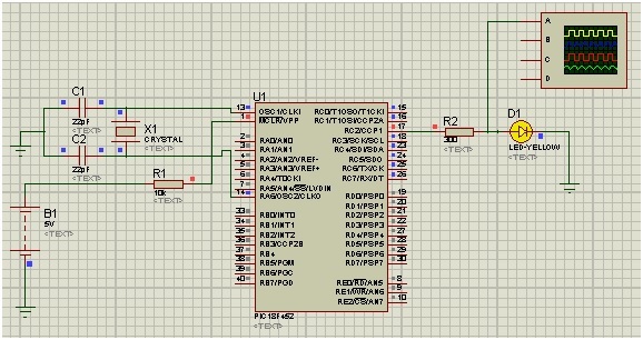
WAVEFORM: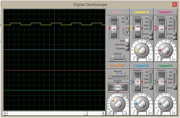
CODE of CCP module of pic microcontroller
void main() {

         PORTC = 0x00;      // Configure Port C as output

         TRISC = 0x00;

     CCP1CON =0x0B;        //module is configured for Compare mode,

// Trigger special event (CCPIF bit is set)

         CCP1IE_bit = 1;

GIE_bit = 1;                         // Enable The Global Interrupt

PEIE_bit = 1;


         CCPR1H = 0xC3;                       // counter value assigned to CCPR1 Register

         CCPR1L = 0x50;                         // Since CCPR1 = 0xC350 = 50000


         T1CON = 0x01;                          //Prescaler 1:1, start Timer 1


while(1){

            //Do whatever else  required

         }

}

void interrupt(){

if (CCP1IF_bit == 1){

               RC2_bit = ~ RC2_bit;        //Toggle RC0 (LED)

               CCP1IF_bit = 0;

         }

}
So this is all about CCP module of pic microcontroller, if you feel any problem while writing code feel free to comment on this post. thanks