
OVERVIEW OF CHARGE TIME MEASUREMENT UNIT (CTMU) OF PIC MICROCONTROLLERS; the one of the peripheral of PIC microcontroller which is charge time measurement unit (CTMU).It is useful for error applications. The heart of CTMU is the constant current source ranges from 0.55µA,5.5µa and 55µA source and each range are can be trim-able up to +/- 62%.The channels of CTMU works in conjunction with an analog-to-digital converter(ADC). It is also used for high precision time measurement asynchronous to the system such as flow meter and other military applications. There are different types of triggering in CTMU. It can be triggered by external or internal sources like timer1, output compare or software trigger. Also, it can be triggered by rising and falling edge combination of one or two external pins. It has precise time delay output. The brief explanation is described by below block diagram. It is the high-level block diagram of CTMU.The ON and OFF is controlled triggering process like as external edge trigger pins. The CTMUCON and CTMUICON are used to set up the operation of CTMU.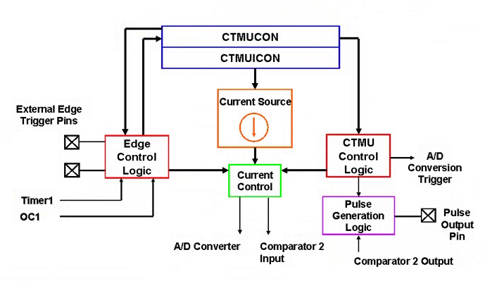
FIGURE 1 BLOCK DIAGRAM OF CTMU
Table of Contents
CURRENT SOURCE TRIGGERING in CTMU OF PIC MICROCONTROLLER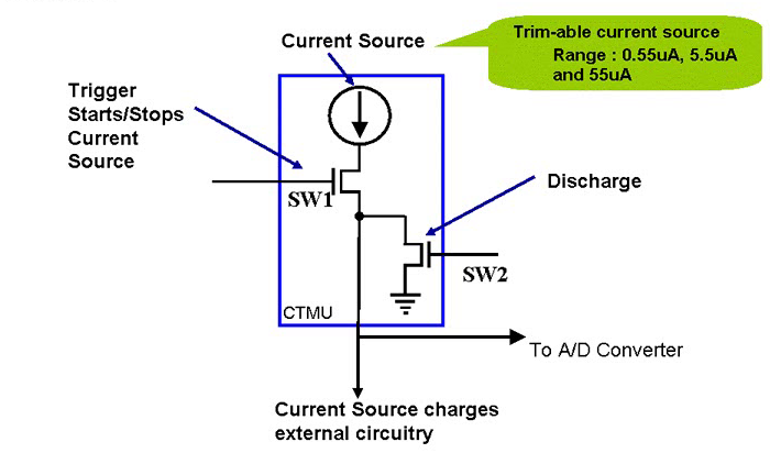
FIGURE 2 CURRENT SOURCE TRIGGER IN CTMU
In the above diagram, current source triggering is shown. The SW1 is triggered by ON and OFF current source and SW2 is makes sure that charging and discharging of the current source to external circuitry.
CTMU INTERFACE WITH A/D
The below diagram shows the CTMU device mounted on A/D converter. It can be observed that when channels are chosen then multiplexer is connected CTMU to an external pin. When the application is ready to make measurement than the CTMU trigger to A/D converter to start occurring sample. It is easy to use these peripherals in any application because of interfacing CTMU with A/D converter.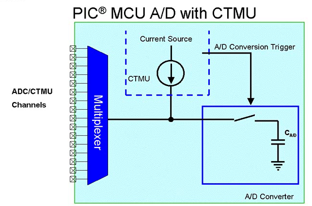
FIGURE 3 ADC INTERFACE WITH CTMU
CAPACITIVE TOUCH APPLICATION WITH CHARGE TIME MEASUREMENT UNIT
To describe this recall some electrical basics. The equation of instantaneous current in a capacitor which is:
i = C . dv / dt
If we kept current constant i.e. I=constant then
I = C . v / t
This gives us the conclusion that if I and t are constant then when capacitance(C) increases the voltage will be decreased. This principle is used in the capacitive touch application.
Capacitive touch theory:
In this the process of PCB material with the copper pad. The FR4 acts as PCB dielectric material. When a copper plate is placed on the PCB. It acts as the one of the conducting plates of the capacitor and the ground plate (second plate) is the PCB pad as shown in below diagram. The larger the plate larger the sensitivity and sensor mode touches easily detectable. The sensor capacitance is indicated by CPU observed from the diagram. When a finger is introduced on the sensor it acts second capacitance as parallel with the pad capacitance. So here comes the task of CTMU which is to detect the change in capacitance when human finger the PCB pad or capacitive switch. We consider it as capacitor switch.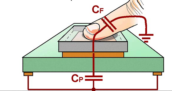
FIGURE 4 CAPACITIVE TOUCH THEORY
CTMU TOUCH CIRCUIT COMPONENTS
In the below diagram it can be observed as the constant current source in the CTMU charges the capacitor sensor for a fixed time and this charging or discharging is controlled by a trigger in the CTMU. The total capacitance of sensor includes sensor capacitance, traces capacitances due to circuit and capacitance due to A/D converter as shown in the below diagram. The ranges for CPU is 30pF.The human body has the ability of 7pF to 20pF capacitance. The total sensor capacitance will be 37pF in this example. The typical time to charge the capacitors is 4 to 5µsec.A/D converter is used to charge build up. Now taking the example in which touch and untouched conditions are explained practically.
I = C. V/ t
UNTOUCHED CONDITION:
- I=5.5µA
- T=10µsec
- Cp=30pF
V=1.833
It is the voltage build up when it is untouched.
TOUCH CONDITION:
- I=5.5µA
- T=10µsec
- Cp=Cp+=37pF
V=1.486
In touch condition, the sensor capacitance is added to the total capacitance. The ADC measures these voltages and it is useful that when the switch is pressed based on the voltage difference.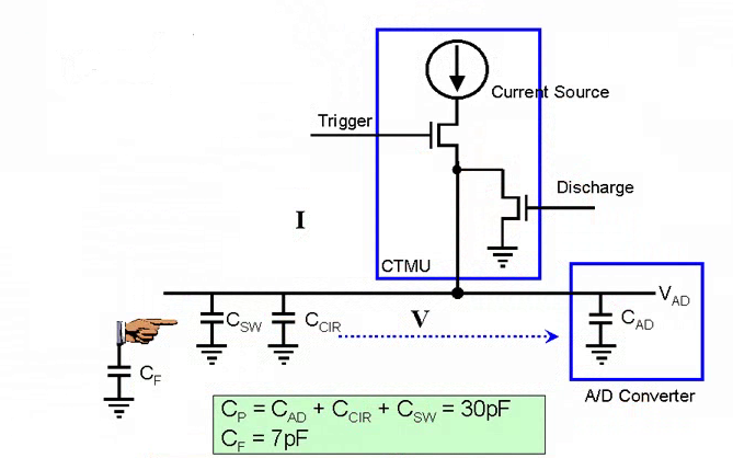
FIGURE 5 CURRENT SOURCE TRIGGERING
CTMU WAVEFORM
FIGURE 6 CTMU WAVEFORM
This shows the complete waveform of CTMU process. First when the channel is discharged so it starts from 0 volts then CTMU starts charging at a fixed time. After that ADC converts charge buildup. As it is observed from the graph that discharges due to the high value of oscilloscope probe leakage.Typically CTMU scans the channels in 6µsec.When the sensor is untouched the charge build up is higher than when it is touched.These conditions can be observed from below graphs. The ADC measures the voltage levels and deceits these conditions.

FIGURE 7 TOUCH AND UNTOUCH WAVEFORM
CTMU APPLICATIONS
There are some other applications of CTMU which are as followed:
- Time Domain Reflectometry(TDR)
- Temperature measurement
- Humidity measurement
- Precise Time measurement
- Absolute and relative capacitance measurement
- Digital to Analog Converter (DAC)
TIME DOMAIN REFLECTOMETRY (TDR)
It means the signal passes through cable and reflects back to the source. In the below example that 50ohms resistance and 50ohms impedance. It is used to measure the length of transmission lines. It is observed from the diagram that there are transmission line R0 and impedance Z0 and determination resistance of Rt. If we take the rising edge of the occurring pulse at reference point time then the voltage is shown in below figure where VIP is the amplitude of the pulse. At time t=0ns it is the time where propagation legs down then the voltage at the node is given in the diagram.
FIGURE 8 TIME DOMAIN REFLECTOMETER
 FIGURE 9TIME DOMAIN REFLECTOMETER
These are two graphs showing un-termination of time.
TEMPERATURE MEASUREMENT USING CTMU
The cheapest way of measuring the temperature the is use of diode. The forward voltages in diode varies with temperature. The usage of constant current source (CTMU) over voltage and temperature, a diode and an A/D converter can measure the temperature up to accuracy of 1 degree Celsius. The below diagram shows the measurement of temperature by using diode and CTMU.The basic equation the for forward current source is observed in the figure. The forward is the constant current source and forward voltage. By measuring forward voltage temperature can be calculated. As it can be observed from figure that CTMU powers the diode by constant current source and ADC measure the forward voltage and temperature is proportional to forward voltage.
FIGURE 10 TEMPERATURE MEASUREMENT
 FIGURE 11 GRAPH OF ADC WITH TEMPERATURE
The above diagram shows the rectifier diode 914 readings. The y-axis is the ADC readings and x-axis is the temperature. As it can be observed ADC readings shows linear response to temperature.
PICDEM TOUCH SENSE2
It is application of capacitive touch sensor pad. This board has an implementation of direct keys, electric keys and linear sliders. Also it has the graphical user interface for diagnosis and customizing purpose. The usage of GUI you can customize our own cap touch sense.
FIGURE 12 PICDEM