
ESP8266 wifi module interfacing with pic microcontroller: Hi everyone I hope you are fine and doing well. In this post, I will guide you how to interface ESP8266 wifi module with pic microcontroller. We will be using pic18f46k22 microcontroller in this post. I have seen many posts on internet on various websites related to interfacing of ESP8266 wifi module with Arduino But I have not found a single post on how to interface ESP8266 wifi module with pic microcontroller. This module can be used to make internet of things based pic microcontroller projects. I have made a project on wifi based home automation system in which I also used esp8266 module. This module can be used in many applications. For example you can use it to send data to server and you can also use to control servo motor from website. It is very easy to interface this module with arduino because there are many resources available online related to Arduino. But in case of pic microcontroller you have to develop your library yourself.
Table of Contents
ESP8266 wifi module configuration
So lets start with pin configuration of this module and how to connect this module with pic microcontroller. This module works on 3.3V voltage range. So make sure you do not connect more than 5 volt with this module otherwise your module will get damaged. It works on serial communication. I will further explain it in later part of this article. This module has six pins as shown in picture below:
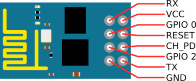
Explanation of each pin along with their operating voltage range is given below.
- Vcc pin: This pin is used to provide power supply. you should connect 3.3V with this pin and voltage more than 3.3 volt burns this wi-fi module.
- GND pin: Connect ground terminal of power supply with this pin
- RX pin: This is a receiver pin of ESP8266 wifi module. This module works on UART serial communication. So this pin is used to receive data from microcontroller or any other device to which you want to send data.
- TX pin: This is a transmitter pin of ESP8266 wifi module. It is used to send or transmit data to microcontroller or any other device which works on serial communication principle.
- GPIO_0 and GPIO_2 : These are general purpose input output pins which are used to directly interact with external digital world. This module can also be used as a stand along device to make IOT based projects. But I will not discuss this aspect in this article. I will write a separate article on it. But in today’s article, I will write only on how to interface ESP8266 wifi module with pic microcontroller.
- RESET pin: It is used to reset this module. It is active high pin and it will reset the module when you apply 3.3 volt.
- CH_PD pin: Connect 3.3 volt of this pin.
So now you got basic understanding and pin configuration of this module. Now lets move to interfacing part that is how to interface esp8266 wifi module with pic microcontroller.
ESP8266 wifi module interfacing with pic microcontroller
To interface this module with any microcontroller and any digital device you should know about operating voltages of this device and microcontroller. As I mentioned earlier, operating voltages of ESP8266 wifi module is 3.3 volt. So its transmission and receiver signal will be also be 3.3 volt amplitude. So when you are connecting this module with any pic microcontroller, you need to make sure either both have same operating voltages or you need to connect any circuit with esp8266 and pic microcontroller. This circuit should be cable of converting 3.3 volt signal to 5 volt and 5 volt signal to 3.3 volt. you can also use voltage divider for this purpose. I will explain it in more details in coming paragraphs.
We are using pic18f46k22 pic microcontroller in this post. Operating voltages of this pic microcontroller is 5 volt. So we need to use any circuit between ESP8266 wifi module and pic microcontroller. We can use a voltage divider between Tx pin of pic microcontroller and Rx pin of ESP8266 wifi module. Voltage divider will step down 5 volt signal of pic microcontroller transmitter to 3.3 volt which is in range of operating voltages of wifi module. We can connect transmit of wi-fi module directly with pic18f46k22 microcontroller, because this pic microcontroller have wide range of operating voltages between 3.3V and 5 volt. So there is not need of voltage divider between Rx pin of esp8266 and pic 18f46k22 microcontroller, because microcontroller will read 3.3 volt as a high signal. But we need to connect voltage divider between Tx pin of microcontroller and Rx pin of esp8266, Because wi-fi module can not read 5 volt and it will burn our module. Interfacing connections are shown below:
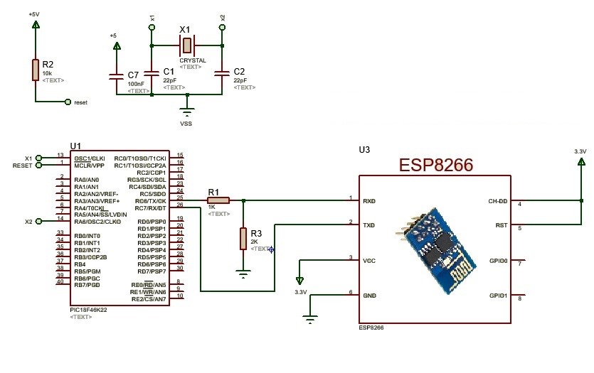
As shown in above circuit diagram, we have connected 1k and 2k resistor between Tx pin of microcontroller and Rx pin of esp8266. I assume you already familiar with voltage divider working principle. If you do not know, you can use a dedicated chip as 5 volt to 3.3 volt converter. Pic microcontroller and esp8266 wifi module communicate with each other through UART serial communication. So you should know how to use serial communication of pic microcontroller. ESP8266 wifi module responds to “AT” commands. you should check data sheet of this module to know more about AT commands, you will send at commands to this wifi module from pic microcontroller through serial communication. Before using AT commands you should set the Baud rate of this module to 9600 because by default baud rate of this wifi module is 115200.
AT+ UART_DEF = 9600, 8,1,0,0