
Flame sensor interfacing with pic microcontroller, In this post on flame sensor interfacing you will learn, how to interface flame sensor with pic microcontroller. This post can be further used as in any flame detection related embedded system project. I have already posted a article on how to interface flame sensor with Arduino Uno R3. If you don’t know what is Arduino, you may like to check our getting started post on Arduino Uno R3. So lets come back to main topic of this post. First we all to understand how to interface flame sensor with pic microcontroller, you should know what is pic microcontroller? you should also know about programming of pic microcontroller? Which compiler is used for programming? How to upload code to pic microcontroller?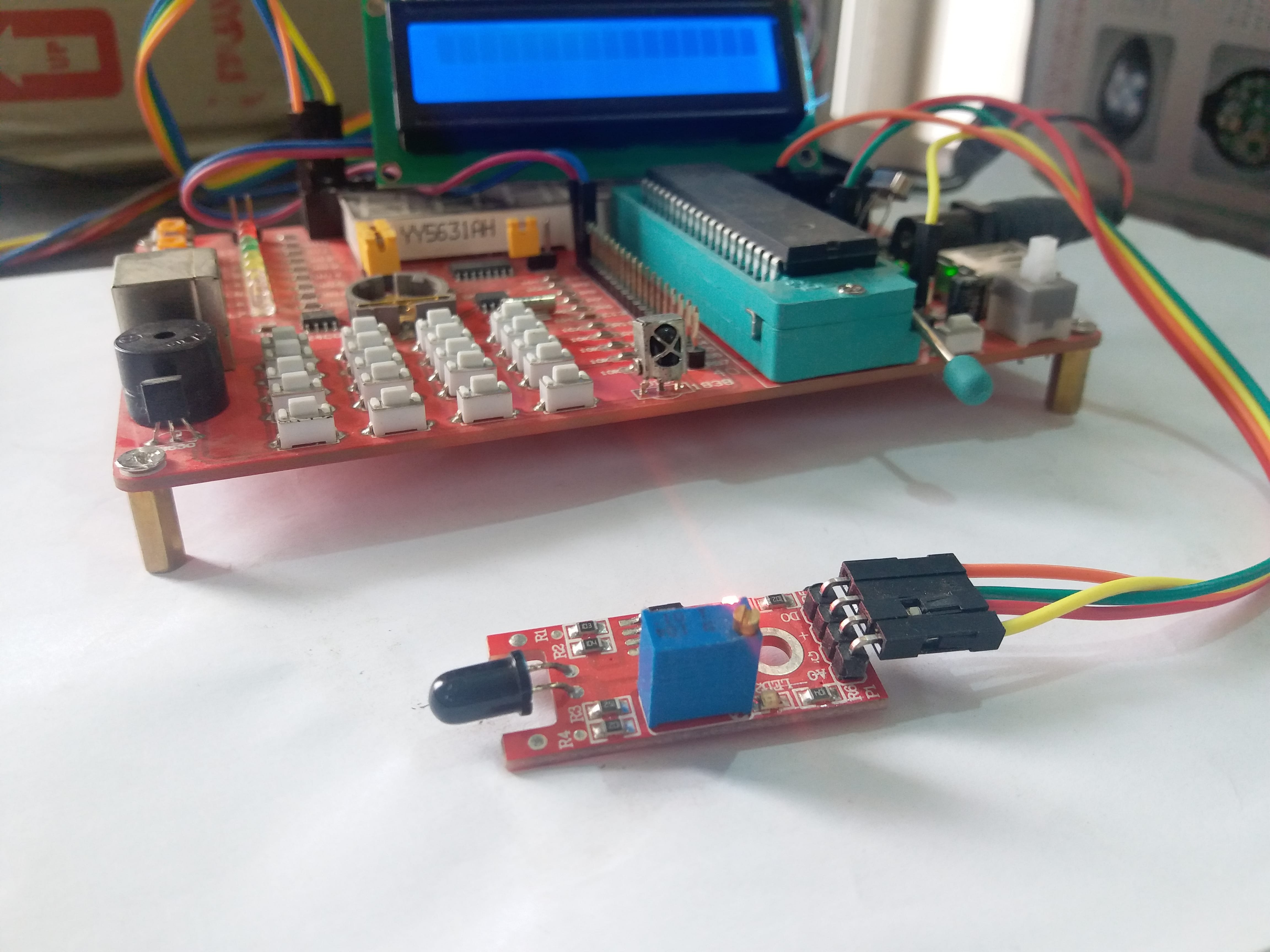
How to use input output ports of pic microcontroller? And how to use analog to digital converter of pic microcontroller. I recommend you to check these posts first:
- Introduction to 8 bit pic microcontrollers
- Introduction to PIC16F877A microcontroller
- Programming of pic microcontrollers
- Types of pic microcontroller compilers
- How to use Mikro c for pic compiler
- How to upload code to pic microcontroller
- How to use input output ports of pic microcontroller
- How to measure analog voltage with pic microcontroller
In this post, I am using PIC16F877A microcontroller which is a 8 bit microcontroller and belong to to mid range family of pic microcontrollers. I am using Mikro c for pic compiler to write code and Pic kit 3 is used to upload code to pic microcontroller. I am using a pic microcontroller development board. But you can make this circuit on bread board as well. So let’s start with basic introduction of flame sensor.
Table of Contents
Introduction to flame sensor
There are many types of flame sensors available in market but I am using IR infrared flame sensor module in this post. Picture of this flame sensor is shown below. As you can see in picture, the main component of this sensor is IR receiver that is photo diode. This photo diode is used to detect flame and fire. You must be thinking, how an IR receiver can detect a fire or flame. I must have gone crazy. No I am not crazy. Let me tell you how its works. Whenever, flame emits or fire burn in surrounding, it emits small amount of infrared lights, these infrared light are used to detect flame or fire by this IR based flame sensor.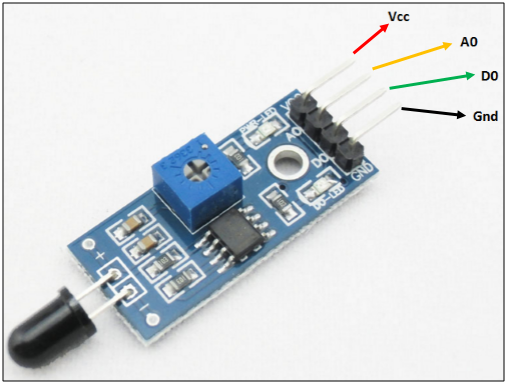
Flame senor IR receiver collects these IR ways waves emits due to fire burning. This IR receiver is connected with operation amplifier which provides the output in the form of voltage at the output of this sensor. We will simply connect this output with pic16f877a microcontroller and process this information to turn on alarm or buzzer which we will connect with pic microcontroller as a output. So whenever fire or flame is detected around flame sensor. Output pins goes high and you will notice 5 volt at the output pin D0 of sensor and when no fire is detected output pin D0 will give logic low or zero volt.
Flame sensor pinout
As shown in above diagram. It have four pins. Functionality of each pin is given below:
- Vcc pin: It is a power supply pin. The operating voltage of this sensor is 3.3 volt to 5 volt. But I recommend you to connect 5 volt to this pin to avoid any compatibility issues with microcontroller.
- Ground pin: you should connect this pin with ground terminal of power supply. Remember ground of pic16f877a microcontroller and flame sensor should be same if you are using different power supply for flame sensor and microcontroller
- A0 pin: It is an analog voltage output pin. Voltage across this pin varies according to intensity of fire or flame. But if you are designing only a fire detector circuit using this flame sensor. I recommend you to use other output pin (D0).
- D0 pin: This is a digital output pin. I have already discussed about it earlier.
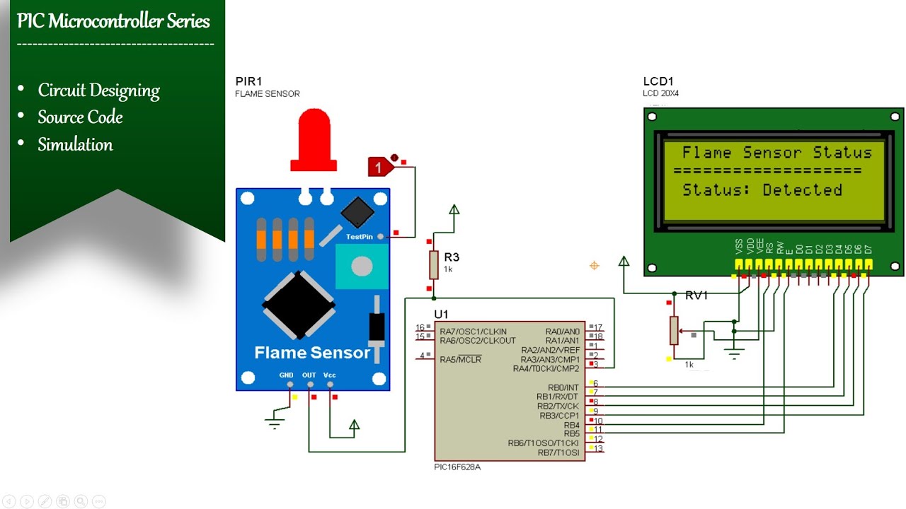
Interfacing flame sensor with pic microcontroller
So lets see how we can interface flame sensor with pic microcontroller. As I have mentioned earlier, I am using pic16f877a microcontroller in this post. To connect with this with pic microcontroller, we need to select any digital input output pin of pic16f877a microcontroller. As shown below I have connected , I/O pin D0 with RD0 pin of PIC16F877A. RDO is a pin number zero of PORTD of PIC16F877A. In programming, we will declare this pin as a input. Because we want to detect logic high and low of flame sensor. Rest of the connections are self explanatory. I have connected a buzzer with PORTC pin number zero. Buzzer will be used as a output. Whenever flame sensor detects a fire, microcontroller will turn on this buzzer or alarm.
Code for flame sensor interfacing with pic16F877A microcontroller
Code for this project is written using Mikro c for pic compiler. To write code for this project, we need to use one pin of pic16f877a as a digital input pin and one pin as a digital output pin. Because PIC16F877A microcontroller captures the output of flame sensor as a input and based on this input microcontroller make decision to turn on or turn off buzzer which is used as output device.
void main(void)
{

PORTD.B0=0;
TRISD.B0=1; // PIN NUMBER 1 IS DECLARED AS A INPUT
PORTE.B0=0;
TRISE.B0=0; // PIN NUMBER 1 IS DECLARED AS A OUTPUT
while(1) { // Endless loop


if( PORTD.B0==1)
{
PORTE.B0=1; // it will make buzzer on
}
else
{
PORTE.B0=0; // it will make buzzer off
}
}
}
In above code one pin of pic microcontroller is declared as input and one pin is declared as a output. Conditional statement check if flame sensor output is high or low. If flame sensor output is high, it will turn on buzzer, otherwise relay remains off.