
How to Use PICKit3: This post is about how to use a burner for programming of pic microcontrollers. I have already posted a article on how to use MikroC for pic for programming of pic microcontrollers in c. The programmer is a debugger system used for software and hardware development of Microchip PIC microcontrollers. The debugger system executes code like an actual device because Instead of using a special debugger chip for emulation it uses a device with built-in emulation circuit. All available features of a given device are accessible interactively, and can be set and modified by the MPLAB IDE interface. I recommend you to check this list of pic microcontroller posts. You can also check a complete list of pic microcontroller projects.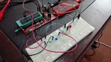
Video lecture on how to upload code to pic microcontroller
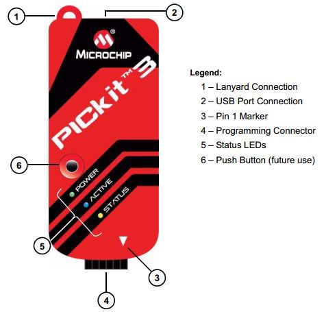
Pickit3 comes with following components.
- Lanyard Connection
- USB Port Connection
- Pin 1 Marker
- Programming connector
- Status LEDs
- Push Button
Lanyard Connection:
A convenient lanyard connection is provided on the programmer.
USB Port Connection:
The Port connection is a USB mini-B connector. It is used to connect the PICKit3 with PC through USB cable.
Pin 1 Marker:
It indicated the location of Pin 1 for proper connection with minimum developer board on which PIC microcontroller is placed.
Programming Connector:
It is a six pin connector and is used to connect the target device with PICKit3. It consists of following pins with pin 1 starting from marker.
- Vpp/MCLR (Power)
- VDD Target (Power on Target)
- Vss (Ground)
- ICSPDAT/PGD (Standard COM Data)
- ICSPCLK/PGC (Standard COM Clock)
- LVP (Low Voltage Programming)

Status LED:
Three LED’s are provided on PICKit3. Different colors indicate different status of PICKit3 as follows:
- Power(Green)
Power is supplied to the PICKit3 through USB port.
- Active (Blue)
Communication link is active and PICKit3 has connection with PC through USB cable.
- Status
Busy (Yellow)
Some function is in progress and PICKit3 is busy with it like programming
Error (Red)
The PICKit3 encounter some error.
Connection with PIC Microcontroller:
To connect the PICKit3 with PIC Microcontrollers following connection are used
- Pin 1 of burner with Pin4 of PIC Microcontroller
- Pin 2 of burner with Pin14 of PIC Microcontroller
- Pin 3 of burner with Pin 5 of PIC Microcontroller
- Pin 4 of burner with Pin 13 of PIC Microcontroller
- Pin 5 of burner with Pin 12 of PIC Microcontroller
- Pin 6 is not connected for normal usage.

This configuration is only for PIC18F1x20. For every microcontroller pin configuration will be different and you can consult datasheet of your respective microcontroller for this these connections.To connect this programmer with programming board consult following picture for help.
Usefulness of PICKit 3 Programmer:
- Debug your application on your own hardware in real time
- Debug with hardware breakpoints
- Set breakpoints based on internal events
- Monitor internal file registers
- Emulate at full speed
- Program your device
Programmer Board Pin OUT:
Programmer board is provided with 6 out output pins at one side for connections with PICKit3. Following are the pins.
- Vpp/MCLR (Power)
- VDD Target (Power on Target)
- Vss (Ground)
- ICSPDAT/PGD (Standard COM Data)
- ICSPCLK/PGC (Standard COM Clock)
- LVP (Low Voltage Programming)

Connecting Programmer Board with PICKit3:
Place you controller on programmer board and then connect it with PICKit3 as follows. Pickit3 pins counting starts from arrow marker.
- Pin 1 of PICKit3 with MCLR of Programmer Board
- Pin 2 of PICKit3 with VCC of Programmer Board
- Pin 3 of PICKit3 with GND of Programmer Board
- Pin 4 of PICKit3 with PGD of Programmer Board
- Pin 5 of PICKit3 with PGC of Programmer Board
Pin 6 is not connected for normal usage.
Connecting Microcontroller with Programmer Board
Following connections are used in Programmer board and PIC18F46K22
- MCLR of Programmer Board with Pin 1 of PIC18F46K22
- VCC of Programmer Board with Pin 11 of PIC18F46K22
- GND of Programmer Board with Pin 12 of PIC18F46K22
- PGD of Programmer Board with Pin 40 of PIC18F46K22
- PGC of Programmer Board with Pin 39 of PIC18F46K22
Pin 6 is not connected for normal usage
These connections are only for PIC18F46K22. For other microcontrollers consult data sheet of respective microcontroller.
Circuit for Project:
Connect the following circuit. You don’t need to connect Crystal oscillator and capacitor. Jus connect LEDs, Power and resistors. You will provide connections from programmer board to LEDs.
Software Part:
- After all connections download MPLAB IPE software can be found easily on internet and install it. Also install drivers for it when prompted.
- Now start mikroC PRO for PIC software and write a small program as follows
- We will use two LEDs. One in sinking mode and one in sourcing mode. For sinking mode writing 0 turns OFF LED and writing 1 turns ON LED. For sourcing mode Writing 1 turns OFF LED and writing 0 turns ON LED.
- After writing the program generate .hex file as explained in post 1.
- Connect Programmer board with PC through USB cable.
- Now start MPLAB IPE software. You will see an interface like below. Select your respective microcontroller. Then click connect. When prompted click OK.

- Wait for output section to show something like this one.

- Go to file on menu bar click import then hex.

- Now go to the same folder where you saved .c file for your mikroC program and open .hex file.

- After that click on program button and you will see the result in the form of LED Blinking.