
KEYPAD INTERFACING WITH PIC MICROCONTROLLER,In this post, you will learn a very simple method of interfacing a keypad with PIC microcontroller. Before we begin with the lesson of keypad interfacing, it is assumed that you know how to interface an LCD with PIC16F877A microcontroller. If you Don’t know about how to interface LCD with PIC16F877A microcontroller. Check this article :”LCD interfacing with PIC16F877A microcontroller
TASK
To interface a keypad with PIC16F877A and display the pressed digits/characters on the LCD.
KEYPAD INTERFACE
Keypad are available in various different sizes. The common sizes include 3×3, 3×4 and 4×4. In this project, we will interface a numeric keypad of 4×4 matrix with the PIC microcontroller 16F877A. The complete circuit diagram, designed on proteus, is given below:
Table of Contents
CIRCUIT DIAGRAM FOR KEYPAD INTERFACING WITH PIC16F877A
Circuit diagram of LCD interfacing with pic microcontroller is given below:
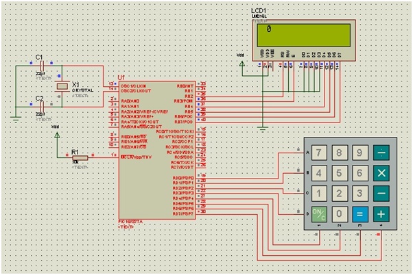
KEYPAD CONNECTION
Make all the connections as shown in the schematic diagram above. Keypad is connected to PORTD of the PIC microcontroller 16F877A. The four rows,namely A, B, C and D, are connected to the lower significant bits of the PORT (RD0-RD3) and the four columns,numbered as 1, 2, 3 and 4,are connected to the MSB of the PORT (RD4-RD7).The LCD module, crystal oscillator and remaining components will be connected to the controller in the similar fashion as described in the previous article.
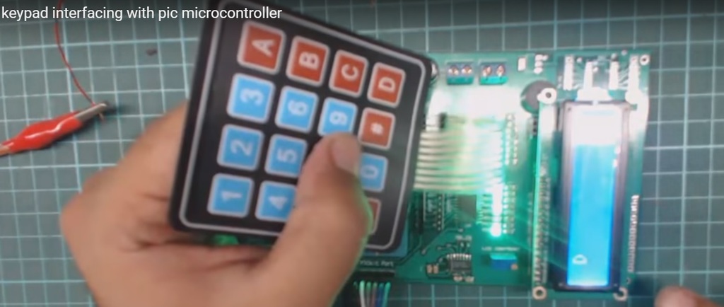
Video demonstration of keypad interfacing
Keypad Mikro c for pic library
Keypad_Init it initializes port for working with keypad. It returns noting. For example
char keypadPort at PORTB;
Keypad_Init();
Keypad_Key_Press it reads the key from keypad when key is pressed. It returns the code of pressed key. If no key is pressed it returns 0. For this port needs to be initialized for working with the Keypad library. For example
char key;
key = Keypad_Key_Press();
Keypad_Key_Click this function is blocking call which means the function waits until some key is pressed and released. When the key is released, the function returns key code from 1 to 16, depending on the key. If more than one key is pressed simultaneously the function will wait until all pressed keys are released. After that the function will return the code of the first pressed key. It returns the code of a clicked key. If no key is clicked it returns 0. For example
char key;
key = Keypad_Key_Click();
C-CODE FOR KEYPAD INTERFACING WITH PIC16F877A
Just like for LCD, MikroC also provides built-in library functions for a 4×4 Keypad. These library routines, however, can be used with other sizes of keypad as well. Functions, such as keypad_init, keypad_key_clicketc, simply needs to be defined in the program, and rest of the inner operations are performed by the mikroC compiler.Write the following code in mikroC to interface keypad with PIC MCU:
 /* KEYPAD INTERFACING WITH PIC16F877A */

int kpi;
// Keypad module connections
char keypadPort at PORTD;
// End Keypad module connections
// LCD Module connections
sbit LCD_RS at RB1_bit; // it can only access a pin not a port
//sbit LCD_RS at LATB1_bit; //same as "sbit LCD_RS at RB1_bit;"
//sbit LCD_RS at LATB.B1; //SAME AS "sbit LCD_RS at RB1_bit;"
//sbit LCD_RS at LATB;
//sbit LCD_RS at PORTB1_bit;
//sbit LCD_RS at PORTB.B1;
//sbit LCD_RS at PORTB;
sbit LCD_EN at RB0_bit;
sbit LCD_D7 at RB5_bit;
sbit LCD_D6 at RB4_bit;
sbit LCD_D5 at RB3_bit;
sbit LCD_D4 at RB2_bit;
// End LCD module connections
// LCD Pin direction
sbit LCD_RS_Direction at TRISB1_bit;
sbit LCD_EN_Direction at TRISB0_bit;
sbit LCD_D7_Direction at TRISB5_bit;
sbit LCD_D6_Direction at TRISB4_bit;
sbit LCD_D5_Direction at TRISB3_bit;
sbit LCD_D4_Direction at TRISB2_bit;
// End of LCD Pin direction
void main()
{
 ANSELH = 0X00;
 TRISB = 0X00;
Lcd_Init(); // Initializing LCD
Lcd_Cmd(_LCD_CLEAR); // Clear Display
Lcd_Cmd(_LCD_CURSOR_OFF); // Cursor Off
Lcd_Out(1,1,"KEYPAD INTERFACE"); // Write "KEYPAD INTERFACE" in the first row
delay_ms(500); // 0.5s delay
Lcd_Cmd(_LCD_CLEAR); // Clear Display
delay_ms(500); // 0.5s delay
Keypad_Init(); // Initializing Keypad
Lcd_Out(1,1,"PRESS A KEY"); // Write "PRESS A KEY" in the first row
delay_ms(500); // 0.5s delay
Lcd_Cmd(_LCD_CLEAR); // Clear Display
do
{
 kpi = 0; // Reset key code variable
// Wait for key to be pressed and released
 do
 kpi = Keypad_Key_Click(); // Store key code in kpi variable
 while (!kpi);
 switch (kpi)
 {
 case 1: kpi = 49; break; // 7-Cmp kpi with equivalent ASCII code of 7, break if equal
 case 2: kpi = 50; break; // 4
 case 3: kpi = 51; break; // 1
 case 4: kpi = 65; break; // Space
 case 5: kpi = 52; break; // 8
 case 6: kpi = 53; break; // 5
 case 7: kpi = 54; break; // 2
 case 8: kpi = 66; break; // 0
 case 9: kpi = 55; break; // 9
 case 10: kpi = 56; break; // 6
 case 11: kpi = 57; break; // 3
 case 12: kpi = 67; break; // =
 case 13: kpi = 42; break; // /
 case 14: kpi = 48; break; // x
 case 15: kpi = 35; break; // -
 case 16: kpi = 68; break; // +
 }
 Lcd_Chr(1, 2, kpi); // Print key ASCII value on Lcd
}
while (1);
}
A variable ‘kpi’ is declared in the beginning of the code, that takes value from the keypad and displays it on the LCD screen.The program first displays‘Keypad Interface’ and ‘Press a key’ on the LCD screen, separated by a 0.5s delay. The program then enters the ‘do-while’ loop and waits for a key to be pressed. As soon as any key is pressed, the inner ‘while’ loop is initiated and the ASCII code of that key is compared with the ASCII codes of all the characters present on the keypad. In case of a match, the program comes out of the while loop, displays the pressed key on the LCD screen and returns to the start of ‘do-while’ loop to wait for the next key press. The process is repeated, until program is aborted.
APPLICATION
Keypads have been used extensively in automotive applications as well as food industries. Programmed Keypads can be used in automated attendance system at schools, offices etc, where you enter your ID, which is displayed and at the same time stored, to mark your presence. Automatic door locks are usually accessed with a keypad control system in which a particular code is dialed on the keypad to open the door.To downlaod circuit diagram and code of above project click on following link: Code and circuit diagramI hope after reading this article, you can use keypad in your project very easily. If you come around any issue after reading this article, your comments are welocme. Kindly share this article with your friends thanks 🙂