
Led matrix interfacing with pic microcontroller: A dot matrix Led display is a 2-dimensional patterned array of LEDs, used to represent characters, symbols and images. It can be used in simple display applications where the resolution is not a big concern.In this post we will learn how to interface Dot matrix LED display with pic microcontroller. We will display some alphabets or number on it.
Table of Contents
LED matrix interfacing working
LED dot matrices are available in various dimensions (7×5,8×8, 7x15etc). 8×8 is shown below which contains 8 rows and 8 columns. An LED is connected between row and column. Each LED is addressed by its row and column number. If row gets positive voltage and column gets negative then only particular LED will glow. If we have to glow LED connected between R2 and C1 from below picture then we have to send 00000010 on row and 11111110 on column.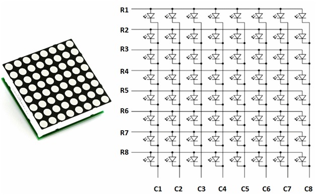
There also happens that LEDs positive is connected to columns and negative to the row.
Interfacing schematic diagram
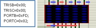
An example of that DOT matrix is shown below. Proteus trial simulations are made to check the connectivity, which showed that rows should provide ground and column should provide a positive voltage to glow that particular LED position. To glow the LED of 1st row 1stcolumn:
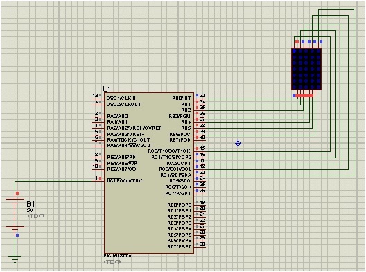
To glow the LED of 2nd row 2nd column:
LED matrix interfacing SWAPPING CATHODE WITH ANODE IN LED MATRIX 5X7 IN PROTEUS
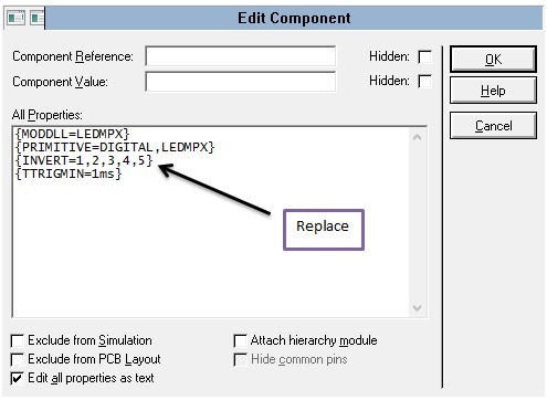
By default the led matrix model in Proteus has cathodes to the rows and anodes to the columns. To change that:
- Right click on the matrix object and open the “edit properties”
- Click “Edit all properties as text”
- Replace{INVERT=A,B,C,D,E,F,G} with {INVERT=1,2,3,4,5}
Now the model will have anodes to the rows and cathodes to the columns.
LED matrix interfacing interfacing to display characters
Firstly connect row and column of LED DOT MATRIX to the microcontroller PORT B and PORT C respectively. Then by using programming we have to send data to first column and at same time we are sending data to rows and then after some milli-seconds we will change the column and send data to row again. We will do this till last column and then repeat it again and again around speed of greater than 20 frames per second. Let’s take an example, If I have to print “I” then the steps followed
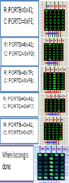
The complete code for above display I through LED interfacing is given by:
void main() {

  TRISB= 0x00;

  TRISD= 0x00;

  PORTB=0x41;

  PORTD=0xFE;

delay_ms(200);

  PORTB=0x41;

  PORTD=0xFD;

delay_ms(200);

  PORTB=0x7F;

  PORTD=0xFB;

delay_ms(200);

  PORTB=0x41;

  PORTD=0xF7;

delay_ms(200);

  PORTB=0x41;

  PORTD=0xEF;

delay_ms(200);

while(1) {

   PORTB=0x41;

  PORTD=0xFE;

delay_ms(15);

  PORTB=0x41;

  PORTD=0xFD;

delay_ms(15);

  PORTB=0x7F;

  PORTD=0xFB;

delay_ms(15);

  PORTB=0x41;

  PORTD=0xF7;

delay_ms(15);

  PORTB=0x41;

  PORTD=0xEF;

delay_ms(15);

     }

       }
DISPLAYING A MOVING CHARACTER with LED matrix interfacing
The trick for stable character was to build one character on the display by scanning the columns very fast and then put it in repetition with delay of milliseconds. If after each 20 frame, we scroll column one position to the left then this will give the effect of a walking text across the dot-matrix display. So firstly we have to build one frame, repeat this 20 times, and after that, read the data one address later, if we do this 5 times (means 5 columns shifting one position left) the character scroll from right to left from the display.
GLOWING FULL COLUMN of LED matrix interfacing
For displaying full column (C1 or any other), the column C1 should be able to sink the high current from 8 LEDs. A pic16f877a microcontroller’s I/O pin cannot sink this much of current, so external transistor arrays are required. For this purpose we can use ULN 2003A IC which has seven built-in Darlington transistor arrays. The inputs of ULN2003A are active high. This means the input pins of this IC must be supplied with logic high in order to bring the corresponding output pins to ground. It can provide 50volt and 500mAmp current in single channel. Input to the column of LED dot matrix is then given by this ULN 2003A IC.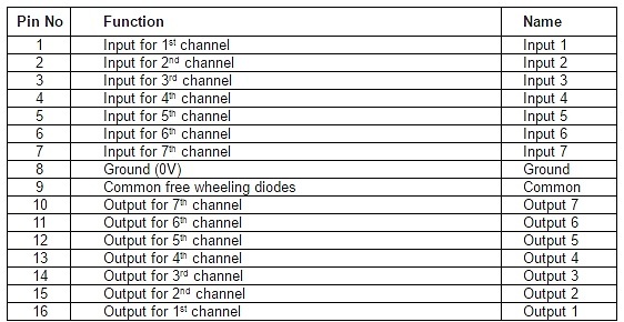
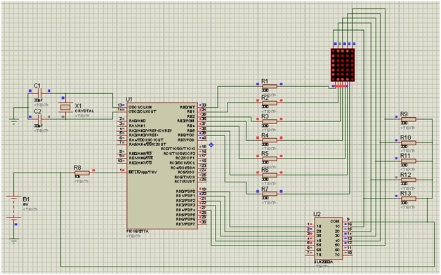
Circuit diagram of LED matrix interacting with pic microcontroller
Port B and Port D of PIC16F877A are used as output port. Port B is connected to rows and D is connected to the input of ULN2003A. For displaying a character we have to give sequences of row and corresponding column values. There will be switching between columns and previous dots disappear. In this case we will not be able to see that particular alphabet. So to avoid it, we start a while loop with 1ms delay. The switching between columns is fast enough to deceive the human eyes and a steady character is displayed.
- MCU (RB0-RB6) to Dot matrix LED (R1-R7)
- MCU (RD0-RD4) to ULN2003A (Pin1-Pin5)
- ULN2003A(Pin16-Pin12) to Dot matrix LED (C1-C5)
CODE of LED matrix interfacing with pic microcontroller
int b[5 ]= {65,62,62,62,93};

intch[10 ]= {254,253,251,247,239};

void main() {

inti;

TRISB=0;

TRISD=0;

while(1)

{

for(i=0;i<5;i++)

{

PORTB=b[i];

PORTD=ch[i];

delay_ms(1);

}

}
We can also use the HEX codes of arrangements as given in previous example. Example: for displaying “A” the code should be {0x7e, 0x09, 0x09, 0x09, 0x7e} and for “B” it is {0x7f, 0x49, 0x49, 0x49, 0x36}
Led matrix interfacing code example number 2
This code t takes in x and y coordinates of an LED and lights up the corresponding LED
#define ROWPORT PORTB
#define ROWTRIS TRISB
#define COLPORT PORTD
#define COLTRIS TRISD

void lightLED(short row, short column);//Prototype

void main() {
 ANSELA=0; ANSELB=0; ANSELC=0; ANSELD=0; ANSELE=0;
 /*Include this line at the top of main,
 this is to turn off the ADC Module.
 It will be explained in detail in the next Lab.
 */

ROWTRIS = 0;
 COLTRIS = 0;
 ROWPORT = 0xFF;
 COLPORT = 0;

 lightLED(1, 2);
 while (1);
}

void lightLED(short row, short column) {
 ROWPORT = ~(1<<row);
 COLPORT = 1<<column;
}
Led matrix interfacing code example number 3
This code will create a pattern as shown in diagram below. It will turn on only diagonal LED’s of LED matrix. 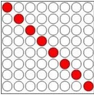
#define ROWPORT PORTB
#define ROWTRIS TRISB
#define COLPORT PORTD
#define COLTRIS TRISD

void lightLED(short row, short column);//Prototype

void main() {
 short i = 0;
 ANSELA=0; ANSELB=0; ANSELC=0; ANSELD=0; ANSELE=0;
 /*Include this line at the top of main,
 this is to turn off the ADC Module.
 It will be explained in detail in the next Lab.
 */

ROWTRIS = 0;
 COLTRIS = 0;
 ROWPORT = 0xFF;
 COLPORT = 0;

 while(1){
 for(i=0;i<8;i++){
 lightLED(1, 2);
 delay_ms(1);
 }
 }
}

void lightLED(short row, short column) {
 ROWPORT = ~(1<<row);
 COLPORT = 1<<column;
}
Led matrix interfacing code example number 4
This code will display letter ‘A’ on Led matrix. you can change code according to your requirement by changing 8×8 matrix array.
#define ROWPORT PORTB
#define ROWTRIS TRISB
#define COLPORT PORTD
#define COLTRIS TRISD

void lightLED(short row, short column);//Prototype

const short H[8][8]={
{0,1,1,1,1,1,1,1},
{1,0,0,0,0,0,0,1},
{1,0,0,0,0,0,0,1},
{1,0,0,0,0,0,0,1},
{1,1,1,1,1,1,1,1},
{1,0,0,0,0,0,0,1},
{1,0,0,0,0,0,0,1},
{1,0,0,0,0,0,0,1}
};
void main() {
 short i = 0, j=0;
 ANSELA=0; ANSELB=0; ANSELC=0; ANSELD=0; ANSELE=0;
 /*Include this line at the top of main,
 this is to turn off the ADC Module.
 It will be explained in detail in the next Lab.
 */

ROWTRIS = 0;
 COLTRIS = 0;
 ROWPORT = 0xFF;
 COLPORT = 0;

 while(1){
 for(i=0;i<8;i++){
 for(j=0;j<8;j++){
 if(H[i][j]){
 lightLED(i, j);
 delay_us(500);
 }
 }
 }
 }
}

void lightLED(short row, short column) {
 ROWPORT = ~(1<<row);
 COLPORT = 1<<column;
}
You may also like to read:
- MAX7219 8-Digit LED Display Driver
- 8×8 LED Matrix Interfacing with MAX7219 and Pic Microcontroller
- 1388A – 8×8 LED Matrix Module
- What is Led matrix? Types of Dot matrix display with working