
PIC Microcontroller Comparator: If we talk about the comparator in electronics language, then it is an analog device, which compares the two signals that could be in the form of voltage or current. In these two signals one may be a triangular wave, saw tooth wave or any other wave and second one may be steady state dc voltages or any other and for comparing these two signals the voltage level of both should be different. The output of the comparator is digital signal which shows, which one is large. The analog comparators are used in many applications. Here we would be talk about the comparator, that is built in pic microcontroller for multiplexing or comparing the inputs with the I/O pins, which saves the cost and make easy to design.
Control Register of pic microcontroller Comparator
The PIC microcontroller consists of a CMCON control register, which have seven bits shown in figure

Figure 1 Comparator Control Register
Bit 7 (C2OUT): The bit 7 in this pic microcontroller comparator control register 7 shows the comparator 2 indication output, which would be 1 when the Vin+ is grater then Vin- in mathematically words 1=C2Vin+ ˃ C2Vin-, similarly the comparator would be shows the output 0 when the Vin+ is less then Vin- same in mathematically words 0 = C2 Vin+ ˂ C2Vin-.
Bit 6 (C1OUT): This is comparator 1 indication output bit, the working of this comparator is same as comparator 2. This bit shows 1 when input 1 is greater than input 2 and shows 0 when input 1 is less than input 2. In mathematically words it shows that ,1 = C1Vin˃ C1in- and 0 = C1Vin˂ C1Vin-
Bit 5,4 (U-0, U-0): These are the unimplemented bits, during the working of comparator, the control register reads these bits as a 0.
Bit 3 (CIS): This bit is actually control input switch, which is used for controlling the input, output modes of comparator.
Bit 2,1,0 (CM2, CM1, CM0): These are the comparator mode of control, which are controlled by the CIS switch bit.
Table of Contents
Configuration Modes of pic microcontroller Comparator
The pic microcontroller comparator works in eight modes and these modes are selected by the CMCON control register. The TRIS register in controller controls the direction of data, which shows by the input, output of pins controller. Once if we changed the comparator mode of operation then, this output level would not be valid for other mode of operation because each device has different electrical specification or output level.one thing should be keep in mind, when we are changing the mode of operation of comparator then, the comparator interrupt should be must disable, otherwise the comparator would be shows the false interrupt. The comparator mode of operations is shown in figure 3 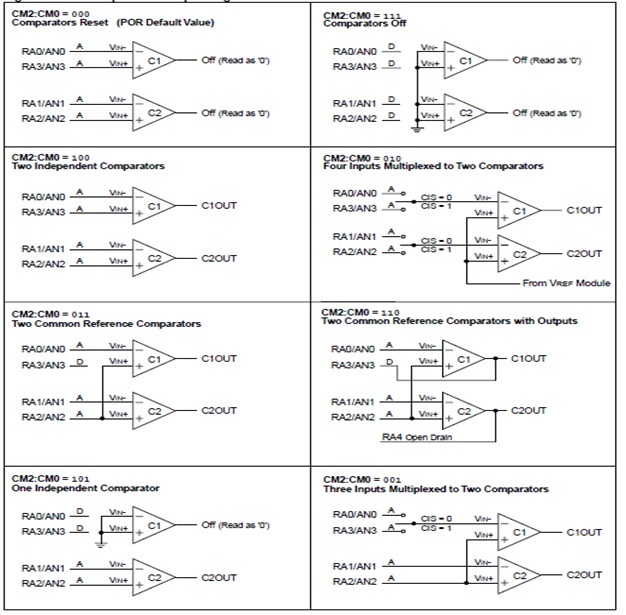
Comparator Modes of Operations
Mode 1: In mode one, the both comparators would be reset and for reset the comparators, the digit 0 0 0 is applied on bits 2,1 and 0.
Mode 2: In mode two, the both comparators would be off and for this mode the digit 1 1 1 is applied on bits 2,1 and 0.
Mode 3: In mode three, the both comparators would be act independently and for this mode the digits 1 0 0 is applied on bit 2,1 and 0.
Mode 4: In mode four, the both comparators work in multiplexing mode, means the four inputs are multiplied into two input and for this mode the digit 0 1 0 is applied on bits 2,1 and 0.
Mode 5: In mode five, the both comparators use common reference signal and for this mode of operation the digit 0 1 1 is applied on bit 2,1 and 0.
Mode 6: In mode six, the both comparators use the output signal as a reference signal and for this mode of operation the digit 1 1 0 is applied on control register bits 2,1 and 0.
Mode 7: In mode seven, the one comparator works independently and second comparator is connected to the ground and for this mode of operation the digit 1 0 1 is applied on control register bits 2,1 and 0.
Mode 8: In mode eight, the two comparator work in multiplexing mode, means in this mode the comparator multiplexes three inputs into two input and for this mode of operation the digit 0 0 1 is applied on control register bits 2,1 and 0.
Operation of Comparator:
A single pic microcontroller comparator along with two analog inputs, which have different voltage level and one digital output is shown is figure 3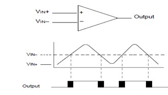
According to the figure 3, the VIN+ and VIN- are the two analog inputs, when the analog input VIN+ is less than analog input VIN-, then the digital output of single comparator would be at low level, in other words this would be at zero level, similarly, when the analog input VIN+ is greater than analog input VIN- then the digital output of single comparator would be at high level, in other words this would be at maximum level. In figure 3 the shaded area represents the uncertainty due to the offset input and response time.
Reference of Comparator:
The reference of comparator is basically an analog signal, that could be internal or external reference signal depends upon the mode of operation of microcontroller comparator. In microcontrollers, the comparator adjusts the digital output signal according to the reference analog input signal. In figure 3, the VIN- signal is compared with the VIN signal, therefore, we can say that the VIN- is the reference signal of single comparator.
Time Response of Comparator:
Time response is the minimum amount of time, which is required to show the guaranteed digital output of comparator after selecting a new reference signal or source voltage. If the internal reference signal is changed, then the settling time also should be considered for desired output. Otherwise the microcontroller’s compotator time response can be used.
Outputs of Comparator:
The outputs of comparator are read through the CMCON control register but these bit can only be read. The comparator output can be directly take from the I/O pins. The I/O pins of comparator are shown in comparator output block diagram.
pic microcontroller Comparator Analog Input Connection
A simple circuit is used for analog input connection of pic microcontroller comparator shown in figure 5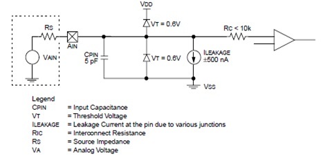
According to the figure the analog inputs are connected to the digital outputs, which have the reverse biased diode. The analog inputs must be attach between the VDD and VSS. In case, the analog input voltage deviates from the range of 0.6 volts in any direction, then one of the diode may be forward biased and latch up may be occurred. 10 KΩ is recommended maximum source impedance for analog source.
Application of PIC Microcontroller Comparator:
1 The Pic microcontrollers are used in three or four stages battery charger, to check the battery voltage at every moment of time. In these charge controllers., the comparator compares the current voltage with the previous voltage to check the battery is fully charged or not.
2 The PIC microcontroller are used in analog to digital converters in which the comparator converter the analog signal into digital signal.