
Rain detector circuit using pic microcontroller , In this post, you will learn how to interface rain drop sensor or rain detector circuit with pic16F877A microcontroller. Rain drop is used to detect the presence of rain in sensitive areas where presence of water can damage the food or other things. So this raindrop sensor can be used to detect the rain in such areas. For example you are sleeping inside your home and you have place your important stuff in open part of your home and you sleep with the assumption that there is no chance of rain tonight. But you know nature does not work according to our assumptions. So if its rains that night, if you do know come to know about it at exact time, your important stuff may get damaged. But if you have installed some kind of rain alarm in outside your room, you can avoid this damage as early as possible. So in this pic microcontroller based project, we are designing a drain detector circuit using pic microcontroller and very famous raindrop sensor.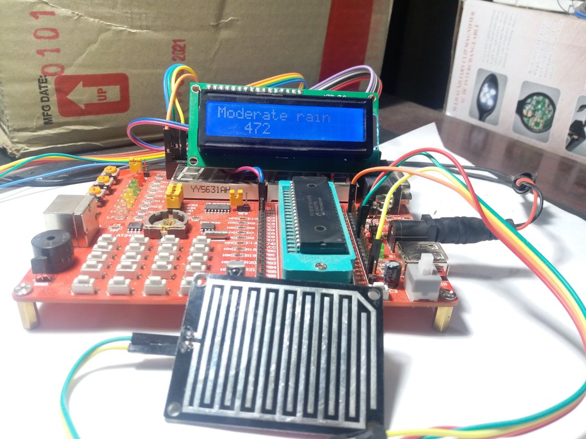
It is a very inexpensive circuit and can be easily place in any open part of your home. you can even interface this rain detector circuit with your mobile phone through Bluetooth by interfacing it with microcontroller and can receive notification of rain on your mobile phone through Android app. you can also interface this circuit with GSM Module and whenever rain drop sensor will detect rain, user will receive message or call on his/here cell phone. So now lets start with introduction of rain detector circuit.
Table of Contents
Introduction to rain drop sensor module
Rain detector circuit is designed using this simple rain sensor module. As I mentioned at the start of article rain sensor module is used to detect rain and it can also be used to detect intensity of rain. Picture of rain drop module is shown below. It consists of two parts. One is electronic part which is used to adjust the sensitivity of this module and also provide output in the form of analog voltage. I will explain later how the output of this sensor works with respect to rain intensity. Other part of rain sensor module is raining board as shown in picture below. When rain falls on raining board, value of output voltage changes at the output of sensor. 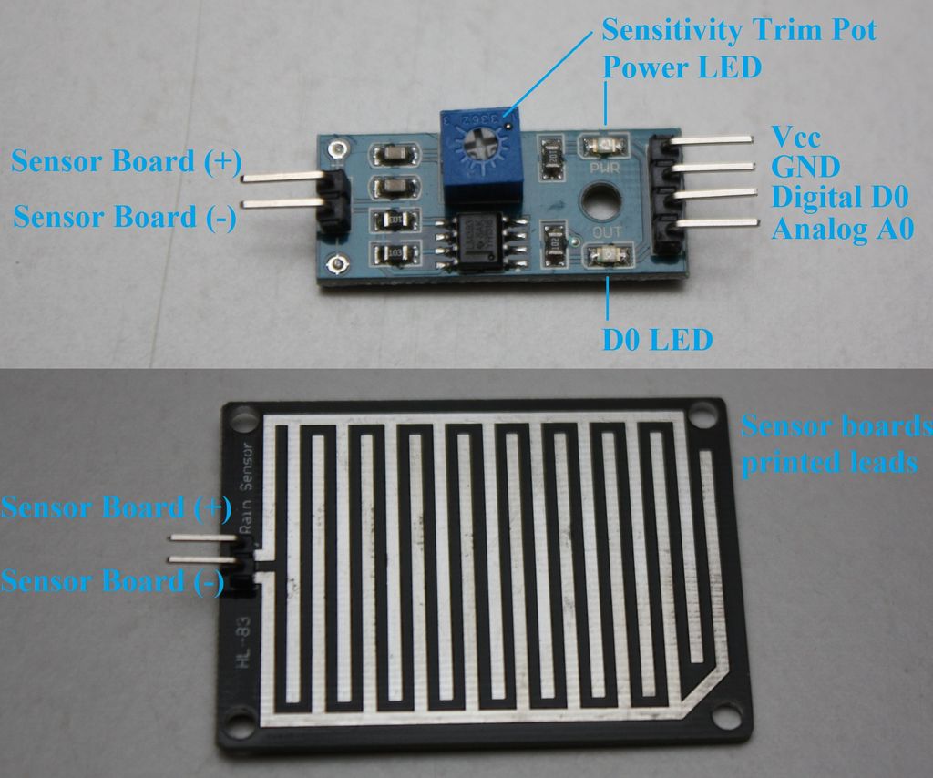
Working of rain detection circuit
This board has on board LED as a indication light and potentiometer to adjust the sensitivity of rain detection module. It provides two types of output one is digital output and other one is analog output. Whenever rain falls on rain pad, digital output goes low and normally digital output will be high and whenever rain falls on rain pad, voltage changes at analog output pin. If you want to measure intensity of rain also, you should use analog output in your project. I am also using analog output of this sensor to interface it with pic microcontroller . You should connect 5 volt to power supply pin of this sensor module and ground with ground terminal of 5 volt power supply. You should clean the sensor, once it detects the rain for you.
So now lets see the working of rain detection circuit with respect to analog output. When there is no rain on the rain detecting pad, the voltage at the analog output will be around 5 volt. This voltage will start decreasing according to intensity of rain. If rain is moderate, around 2.5 to 3 volt will appear at the analog output and if rain is heavy less than 1 volt will appearing across the analog output pin. Remember these are just the rough calculations I made after drooping water droplets on this sensor. The value of output voltage depends on the intensity of rain and both have the inverse relationship with each other. So now lets see how to interface this rain drop sensor module with pic microcontroller to design our complete rain detection module.
Rain detector circuit with pic microcontroller
So now lets see how to interface this rain drop sensor with pic microcontroller. To interface this rain drop sensor with pic microcontroller , you need to use analog to digital converter module of pic microcontroller. Because we want to measure analog voltage of rain sensor which will appear at the analog pin of rain detection circuit. So you should know, how to measure analog voltage with pic microcontroller. IF you don’t know I recommend you to check my article on voltage measurement using pic microcontroller and we will be display status of rain on LCD, so you should also know how to interface LCD with pic16f877a microcontroller
- Voltage measurement using pic microcontroller
- LCD interfacing with pic16f877a microcontroller
Circuit diagram of rain detection circuit or sensor interfacing with pic microcontroller is shown below.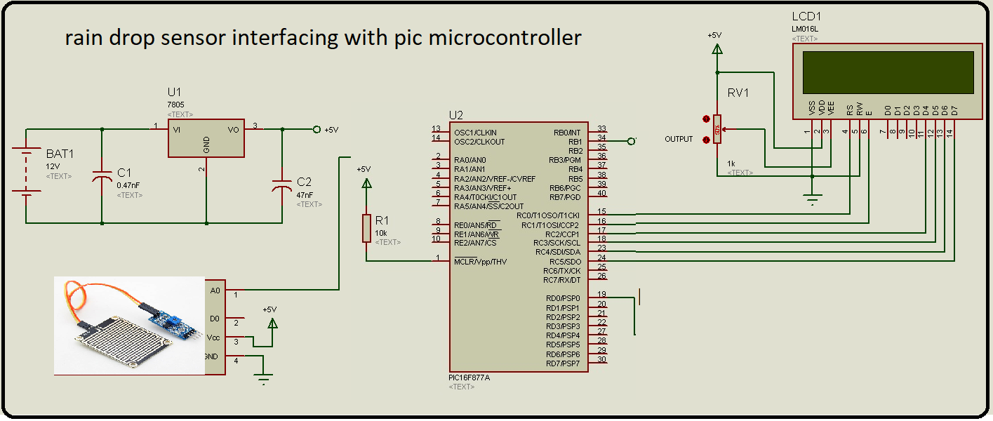
LCD is connected with PORTC of pic16F877A microcontroller which will display the status of rain. If no rain , LCD will display no rain and it will also display the status of moderate rain and heavy rain according to intensity of rain. Output of rain drop sensor is connected with analog pin zero of PIC16F877A microcontroller.
Code of rain detector circuit using pic microcontroller
Code for rain detection circuit with pic microcontroller is written using Mikro C for pic compiler. There are many types of pic microcontroller compilers available but it is my best choice because of many reasons. You simply copy this code and upload it pic16f877a microcontroller using pic kit3 programmer. and make a circuit diagram according to above connections.
// LCD module connections
sbit LCD_RS at RC0_bit;
sbit LCD_EN at RC1_bit;
sbit LCD_D4 at RC2_bit;
sbit LCD_D5 at RC3_bit;
sbit LCD_D6 at RC4_bit;
sbit LCD_D7 at RC5_bit;

sbit LCD_RS_Direction at TRISC0_bit;
sbit LCD_EN_Direction at TRISC1_bit;
sbit LCD_D4_Direction at TRISC2_bit;
sbit LCD_D5_Direction at TRISC3_bit;
sbit LCD_D6_Direction at TRISC4_bit;
sbit LCD_D7_Direction at TRISD5_bit;

////// rain detection circuit sensor variable///////

float rain_value;
char text[10];
void main(void)
{

ADC_Init(); // it will initialize the adc module of pic16f877a microcontroller
Lcd_Init(); // Initialize LCD
Lcd_Cmd(_LCD_CLEAR); // Clear display
Lcd_Cmd(_LCD_CURSOR_OFF); // Cursor off
Lcd_Out(1,1,"Rain sensor" ); // Write text in first
delay_ms(2000);
Lcd_Cmd(_LCD_CLEAR); // Clear display

while(1)
{ // Endless loop

moisture_value = ADC_Read(0); // It will read the moisture value of sensor
if( moisture_value < 300 )
Lcd_Out(1,1, "Heavy rain" );
else if( moisture_value < 500 )
Lcd_Out(1,1, "Moderate rain" );
else
Lcd_Out(1,1, "No rain" );
//***** it will display the rain intensity in percentage format/////////
moisture_value = ( moisture_value * 100) / (1023); // it converts the moisture value on percentage
FloatToStr(moisture_value, Ltrim(text));
Lcd_Out(2,1, text );
Lcd_Out_cp("%");

}
}
So this is all about how to design rain detection circuit using pic microcontroller. you may also like to check followings:
- Moisture sensor interfacing with pic microcontroller
- light dependent resistor interfacing with pic microcontroller
- DHT11 humidity sensor interfacing with pic microcontroller