
SERVO MOTOR interfacing with PIC16F877A MICROCONTROLLER,In this post, you will learn the interfacing of a servo motor with PIC16F877A microcontroller. Programming to control servo motor and hardware connections of servo motor with PIC16F877A microcontroller. Lets start with basic introduction of servo motor, then I will move forwared to its circuit diagram and programming.
What is servo motor?
A servo motor is a special kind of motor that operates upon the given instructions. It provides angular precision, which means,unlike other electrical motors that keep on rotating until power is applied to them and stops only when the power is switched off, the servo motor rotates only to a certain degree or until it is required to and then the motor stops and waits for the next instruction to carry out further action.Servo motors are controlled with the help of servomechanism. Its angular rotation and final movement is dictated by position feedback. The input to its control line determines the position demanded for the output shaft.
TASK
To control the working of a servo motor when interfaced with PIC16F877A microcontroller.
CIRCUIT DIAGRAM FOR SERVO MOTOR INTERFACED WITH PIC 16F877A :
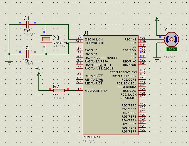
It has a very simple circuit diagram. The control wire of the servo motor is directly connected to the RB0 pin of the microcontroller. This pin will provide the required angular displacement of the motor. In this project, suppose we are working with a servo motor whose angular rotation is limited to 0° 180°.We can control the rotation of the motor within this limit with utmost precision by using a pulse whose width is varied to attain the desired angle.
A pulse is fed to the servo motor after every 20ms (or 20,000us). The angular position of the motor is determined by the length of this pulse. The angular positions 0°, 90° and 180° are demonstrated in the code.
C-CODE FOR SERVO MOTOR INTERFACING WITH PIC MCU
Write the following code of servo motor interfaced with PIC in mikroC Compiler.
void Rotation0() //0 Degree
{
unsigned int i;
for(i=0;i<50;i++)
{
PORTB.F0 = 1;
Delay_us(800); // pulse of 800us
PORTB.F0 = 0;
Delay_us(19200);
}
}
void Rotation90() //90 Degree
{
unsigned int i;
for(i=0;i<50;i++)
{
PORTB.F0 = 1;
Delay_us(1500); // pulse of 1500us
PORTB.F0 = 0;
Delay_us(18500);
}
}
void Rotation180() //180 Degree
{
unsigned int i;
for(i=0;i<50;i++)
{
PORTB.F0 = 1;
Delay_us(2200); // pulse of 2200us
PORTB.F0 = 0;
Delay_us(17800);
}
}
void main()
{
TRISB = 0; // PORTB as Ouput Port
do
{
Rotation0(); //0 Degree
Delay_ms(2000);
Rotation90(); //90 Degree
Delay_ms(2000);
Rotation180(); //180 Degree
}while(1);
}
Individual functions for angular rotation of the motor by 0°, 90° and 180° have been declared in the beginning of the code.In this post, we have not used the actual Pulse Width Modulation feature of PIC16F877A to generate a pulse.Instead, the pulse has been created with the help of delays in the program. The delay duration for a particular angle is equivalent to the length of the pulse required for the motor to rotate up to thatcorresponding angle. That is, for 0° angle, the pulse width is approx. 800ms, so a delay of 800ms is introduced with the PORT pin RB0 set to high. Similarly,a pulse of 1500ms is required for a rotation up to 90° and 2200ms for a180° angle.
In the main program, PORTB is set as an output port and all the three functions are called, separated by a delay of 2000ms between them. The program causes the motor to rotate in a pattern; 0° 90° 180° 0° and so on. This continues in an infinite ‘do-while’ loop, until the program is aborted.
APPLICATION
Servo motor has a large number of application in industries. In industrial manufacturing, the conveyor belt uses servo motors to control the precise movement of the belt. Servo motors are most popular in robotics. The precise angular displacement of a robot’s arm is controlled by a servo motor. The physicalmovement of the solar panel with respect to the sun is also carried out by servo motors in a solar tracking system.
To download circuit diagram and code. Click on following link. Don’t forget to share this article with your friends. Thanks 🙂
Project files