
Configuration Bits:
Some special bits that can only be modified at the time of programming are called configuration bits. Configuration bits specify some of the operating modes of microcontroller. These bits are “read” during the reset and enable or disable the hardware features of microcontroller.
Procedure for setting the configuration bits of PIC16F877A:
- MikroC users can edit these configuration bits by editing the project settings:
Project >> Edit Project
MPLAB users can edit these configuration bits by using Configuration Bits tool.
Windows>> PIC Memory Views>> Configuration Bits

- Settings will be open now:
- Change the MCU Name to P16F877A
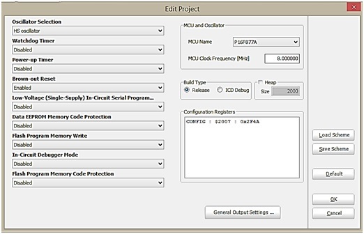
MCU Clock Frequency to 8.00 MHz - The features controlled by configuration bits are:
- Clock Source
- Watchdog Timer
- Power-up Timer
- Brown-out Reset
- Low-Voltage (Single-Supply)
- Data EEPROM Memory Code Protection
- Flash Program Memory Write
- In-Circuit Debugger Mode
- Flash Memory Code Protection
- OSCILLATOR:
It produces a periodic and oscillating waveform (a sine wave or a square wave). Oscillators mainly convert DC from a power supply to AC signal. Oscillator works at a certain frequency, which is usually determined by a quartz crystal. When a direct current is applied to crystal, it vibrates at a frequency that depends on its thickness, and on the manner in which it is cut from the original mineral rock.
For PIC16F877A, Oscillators have upto 4 different modes:
| LP | Low Frequency (Power) Crystal | ||
| XT | Crystal/Resonator | ||
| HS | High Speed Crystal/Resonator | ||
| RC | External Resistor/Capacitor |
The LP, XT, and HS clock modes require an external crystal or resonator to be connected to the microcontroller. The RC clock mode requires an external resistor and capacitor to set the oscillator frequency.Each mode is optimized for a different frequency range. Which mode to be select, it all depends upon the desired output configuration.
LP:
- Selects the lowest gain setting for the internal inverter-amplifier.
- Lowest current consumption of the three modes.
- Designed to drive a 32.768 KHz crystal.
XT:
- Selects the intermediate gain for the internal inverter-amplifier.
- Typically selected for crystals in the range of 4 MHz or lower.
HS:
- Selects the highest gain setting for the internal inverter-amplifier.
- Highest current mode.
- Typically used with crystals above the 4 MHz range.
Operation:
If we select the desired frequency for example 8MHz, then Oscillator must be HS.The crystal is connected to the OSC1 and OSC2 pins of microcontroller. It will also require capacitors on each pin in the range of 15pf-30pf.
- WATCHDOG TIMER:
We can face a situation like if microcontroller is not working properly. In this case, we mostly reset the microcontroller by reset button. But it is not good to use a reset button for solving it every time. To overcome this situation, we use a watchdog timer.Watchdog timer is an electronic timer which is integrated in microcontrollers and is used to detect and recover from above problems.It is a simple counter that gives pulses to restart the Microcontroller unit. The output of the watchdog timer is given directly to the microcontroller reset signal.It is actually a free run counter where our program needs to write zero in every time it executes correctly. Zero will not be written if the program gets stuck and the counter will reset the microcontroller upon achieving its maximum value.
Operation:
Watchdog timer (WDT), when enabled, the processora utomatically resets.
1=Enable WDT
0=Disable WDT
- POWER-UP TIMER:
When a reset occurs, the quick startup of Microcontroller again can cause problems. To avoid such conditions, a fixed start up delay of 72 ms is provided by this timer. It delays the PIC MCU until the operating voltage VDD rises to its full value. So, this process ensures that the supply voltage is stable before the clock starts up.
Operation:
Power-up Timer (PWT), when enabled, creates delay when the device will be in Reset state.
1 = Disable PWT
0=Enable PWT
- BROWN-OUT RESET (BOR):
When a drop in voltage comes or the voltage becomes less than threshold voltage, RAM memory may get corrupted and the device will not run properly, this condition is called Brown out.
Operation:
Brown-out Reset (BOR), when enabled, resets the device if the supply voltage VDD drops below VBOR for time longer than TBOR. Once this situation occurs, the device will remain in Brown-out reset until VDD rises above VBOR.
VBOR about 4V
TBOR about 100 µS
1=Enable BOR
0=Disable BOR
- LOW-VOLTAGE (SINGLE-SUPPLY):
These microcontrollers can be serially programmed. This allows customers to program the microcontroller just before shipping the product. When using ICSP (In-Circuit Serial Programming), it must be supplied at 4.5V to 5.5V. (Usually Higher voltages=8V)
The LVP (low voltage programming) bit of the configuration enables low voltage ICSP programming. It will allow microcontroller to program though ICSP by using VDD source within the operation voltage range. So in short we can say that VDD does not have to bring to high voltage.
Operation:
In this mode, the RB3/PGM pin is dedicated to the programming function.During programming, VDD is applied to the MCLR pin. To enter Programming mode, VDD must be applied to the RB3/PGM provided the LVP bit is set. By default from the factory the LVP bit is set to 1. If Low-Voltage Programming mode is not used, the LVP bit can be programmed to a ‘0’
1= Enabled LVP
0= Disabled LVP
- DATA EEPROM MEMORY CODE PROTECTION BIT (CPD):
PIC 16F877A has an internal EEPROM data. Two bits, CPD and WRTD, protect the entire data EEPROM. External reads and writes of data EEPROM is controlled by CPD. CPD Configuration Bit protect this region of memory against reading and external recordings (i.eIn- circuit Serial Programming)
Operation:
1 = Data EEPROM code protection off (Disable)
0 = Data EEPROM code-protected (Enable)
- FLASH PROGRAM MEMORY WRITE:
These bits enable writing in the flash memory by the use of EECON. We can write data directly into the Flash memory by the device firmware. Simply, we can say that the sectors of our choice can be selected for the recording of data or for the In-circuit Serial Programming.
- IN-CIRCUIT DEBUGGER MODE:
Debugging process allows the execution and tracking the code. This process read variables and execution step-by-step. Pins RB6 and RB7 can be used as in-circuit debugger pins.
Operation:
1=In-Circuit Debugger Disabled
0=In-Circuit Debugger Enabled (RB6 and RB7 are dedicated to the Debugger)
When enabled>>debug process
When disabled>>allows use as digital inputs and outputs
- FLASH MEMORY CODE PROTECTION:
If the program is stored in the flash memory then this bit is responsible for enabling the code protection.
Operation:
Once enabled, the Flash memory (program memory) will be copy and protected. It cannot be read then.
1=Protection Code off (CP Disabled)
0=All Program memory code Protected (CP Enable)