
USING TIMERS IN PIC18F452 MICROCONTROLLER:Timers and counters are important as timers can tell the time and count. Counting and timing allows for controlling the brightness of LEDs, controlling the angle of servo shafts and PWM signal generation etc. All microcontrollers have clocks in them or they use the one that resides outside of a microcontroller. Microcontroller needs clock so our programs can be executed in regularity with the clock. This is the basic function of microcontrollers. The PIC 18F452 is a high performance flash based microcontroller with 32 Kbytes of program memory and 1.5Kbytes of RAM. PIC18F452 has four different timers namely, Timer0, Timer1, Timer2 and Timer3. Some special features of these Timers are given below:
Table of Contents
Types of timers in PIC microcontroller
Timer0:
- Timer0 can work as both 8-bit and 16-bit modes timer/counter
- Software programmable Prescaler
- Select able clock source (internal or external)
- Interrupt on overflow
Timer1:
- Timer1 can work as 16-bit timer or counter
- Readable and writable 8-bit registers (TMR1H and TMR1L)
- Selectable clock source (internal or external)
- Alternate clock source can be provided at Timer1 oscillator pins (T1OSO & T1OSI)
- Interrupt on overflow
- Timer1 can be multiplexed with other peripherals like ADC and generates special event triggering for CCP (Capture, Compare and PWM) events.
Timer2:
- 8-bit Timer and Period registers (TMR2 and PR2, respectively)
- Software programmable prescaler (1:1, 1:4 and 1:16)
- Software programmable postscaler (1:1 – 1:16)
- Interrupt on TMR2 to PR2 match
- Optional use as the shift clock for the MSSP (Master Synchronous Serial Port) module
Timer3:
- Timer3 can work as 16-bit timer or counter
- Readable and writable 8-bit registers (TMR3H and TMR3L)
- Selectable clock source (internal or external)
- Alternate clock source can be provided at Timer1 oscillator pins (T1OSO & T1OSI)
- Interrupt on overflow
- Timer3 can be multiplexed with other peripherals like ADC and generates special event triggering for CCP (Capture, Compare and PWM) events.
Clock source of pic microcontroller timers
The simplest is the TIMER0. For Timer configurations, it is important to know that how time delay is calculated by the timer. Firstly the Timer clock source is set.
- Internal Clock Mode:
The clock can be internal or external. In the internal clock mode Timer0 operates as timer and uses the internal(FCPU) clock with or without pre-scalar. Prescaler is an integer value which divides the CPU clock to give Timer Clock i.e Timer Clock = FCPU/pre-scalar. When the Pre-scalar is set to one or bypassed then the timer runs on the same clock as the CPU is running.
- External Clock Mode:
In this mode Timer0 operates as counter and counts on every rising or falling edge of the clock connected to the Timer’s clock pin.
DELAY CALCULATION of timers
Now we calculate the time delay of 1 sec using 20MHz crystal oscillator with PIC microcontroller. PIC 18F452 has ability for external as well as internal clock source but we are using Timer0 with internal clock (Timer mode).
- Clock source frequency of crystal:
Fosc=20 MHz= 20000000 Hz
- The PIC internally divides FOSC by 4 to get FCPU. Based on this we have clock cycle and instruction cycle. The clock cycle is simply 1/FOSC while instruction cycle is 1/FCPU.
FCPU=20 MHz/4 =5 MHz
- PIC18 has the ability to generate interrupt on overflow. It means that a bit called Timer0 Interrupt Flag (TMR0IF) is set when TMR0 makes transition from 255 to 0.
Prescaler Period (if Prescaler = 1:256)
Ftimer= 5 MHz/256 =19531.25Hz
Single overflow of Timer0 will give this delay:
Ttimer = 1/19531.25 = 0.0000512 sec = 51.2 µs
- This means that when timer runs, it will take 51 µs to increment its value at every count. Now we have to calculate the value to be filled in Timer register to generate 1 sec delay.
No. of count for 1 sec Delay = 1 sec/51 µs = 19531.25 = 4C4B H
The value to be filled in timer’s 16 bit register = FFFF – 4C4B= B3B4 H
These values are filled in the Timer register and it rolls over up to FFFF. The values are reloaded again to start timer for same delay.
TIMERs REGISTERS CONFIGURATION
Every Timer has certain registers associated, which must be configured for desired operations.The Timer register can have the following bit length:
8 bit timers – These can count between 0-255
16 bit timers – These can count between 0-65536
32 bit timers – These can count between 0-4294967296
The registers of Timer0 have been explained below.
Timer0 Control Register: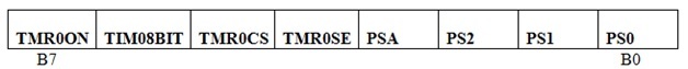
TMR0ON: Timer0 on/off bit
This bit is set to high to enable the Timer0.
1 = Enable the Timer0
0 = to stop Timer0
T08BIT: 8/16 bit mode selection bit
This bit selects the Timer mode.
1 = Timer0 is configured as an 8-bit timer/counter.
0 = Timer0 is configured as a 16-bit timer/counter.
TMR0CS: Timer0 Clock Source set
Timer mode is selected by clearing the TMR0CS bit of the Control register.
1 = T0 Clk
0 = Fosc/4
TMR0SE: Timer0 source Edge select
The rising or falling transition of the incrementing edge for either input source is determined by the TMR0SE bitin the Control register.
1 = Increment TMR0 on high to low transition
0 = Increment TMR0 on low to high transition
PSA: Prescaler Assignment
The prescaler is enabled by clearing the PSA bit of the Control register.
1 = Prescaler not Assigned to TMR0
0 = Prescaler Assigned to TMR0
PS2, PS2, PS0: Prescaler Rate Select bits:
There are eight prescaler options for the Timer0 module ranging from 1:2 to 1:256. The prescale values are selectable via the PS 2:0 bits of the Control register. In order to have a 1:1 prescaler value for the Timer0 module, the prescaler must be disabled by setting the PSA bit of the Control register.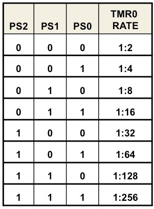
Timer0 Interrupt Control Register:
| GIE | PEIE | TMR0IE | INTE | IOCIE | TMROIF | INTF | IOCIF |
B7 B0
TMR0IE: Timer0 Interrupt Enable
This bit is used to enable/disable the Timer0 overflow interrupt.
1 = TMR0 Interrupt enabled
0 = TMR0 Interrupt disabled
TMROIF: Timer0 Interrupt Flag
This is Timer0 overflow flag bit which is bit is set when TMR0 register overflows. This bit is cleared by the software.
1 = TMR0 has overflowed
0 = TMR0 did not overflowed
TMR0 (Timer0 Register):
This register is divided into registers
- TMR0H
- TMR0L
Both registers are separately accessible thus Timer0 can work in both 8-bit and 16-bit modes. In these registers, pre-calculated value for delay is filled.
WORKING of pic microcontroller timers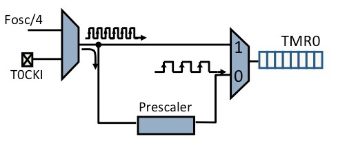
Timer0 can operate as a timer or as a counter. When the clock source is the instruction cycle clock, it operates as a timer and when the clock source is the T0CKI pin, it operates as a counter. When PIC18f452 reads the TMR0L register, the upper half of Timer0 is latched into the TMR0H register. This makes sure that the PIC18 always reads a 16-bit value that its upper byteand lower byte belong to the same time.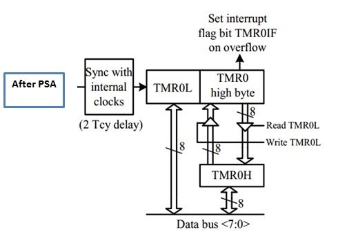
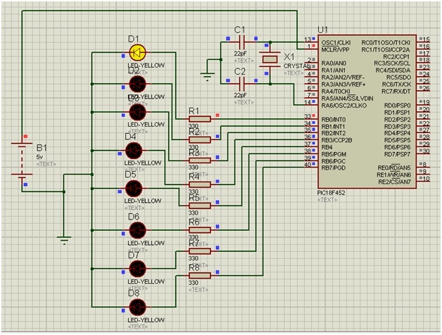
PROTEUS SIMULATIONS of timers
For Programming:
- Firstly through T0CON register, we will select the Pre-scaler, Clock option and Mode of Timer0.
- Then we fill the higher byte of Timer value in TMR0H and then fill lower byte value in TMR0L
- Now set the TMR0ON bit to start the timer.Wait until the TMR0IF flag gets high
- As TMR0IF gets high, we set it to zero and stop the timer by clearing the TMR0ON bit.To start the Timer0 again repeat this process of placing higher byte and lower byte with help of while loop.
The time delay has been establishedhere by glowing a set of 8 LEDs one by one with a delay of 1 sec. The code is also given below.
CODE to generate delay with timers
void main()
{
TRISB=0; // COnfigurePortB as output Port.
LATB=0x01; // Turn on LED on PORT B pin0
T0CON=0x07; // Prescaler= 1:256, 16-bit mode, Internal Clock
while(1)
{
// Values calculated for 1 second delay with 20MHz crystal
TMR0H=0xB3; // Placing Lower byte in TMR0L
TMR0L=0xB4; // Placing Lower byte in TMR0L
T0CON.TMR0ON=1; // Timer0 On
while(INTCON.TMR0IF==0); // Wait until TMR0IF gets flagged
T0CON.TMR0ON=0; // Timer0 Off
INTCON.TMR0IF=0; // Clear Timer0 interrupt flag
LATB=(LATB<<1)|(LATB>>7); // Circular right shift at PortB
}
}
Conclusion:
In this post, we learnt how to use PIC18F452’s Timer0 to obtain a delay of approximately 1sec. Moreover, the timer can also be used to find the execution time of a function.Similarly we can use other timers by carefully considering there data sheets.