In a pic microtroller MID-RANGE MCU FAMILY an internal circuit is used, that is called oscillator for generating the device clock, which is required for executing the instruction and peripherals of the function. For generating the one internal instruction four clock (TCY)periods are used. The internal oscillator might have up to eight different modes. There are two modes, which are used to allow the RC internal oscillator clock out (CLKOUT) to drive the I/O pins or these modes allow the I/O pin to be derive the general purposes instruction. These modes are selected by the device configuration bits, these bits are non-volatile memory locations and their mode of operation is determined by the value written during the programming of device. The oscillator has following modes of operations.
- RC (External resistor)
- HS (High speed crystal or resonator)
- LP (Low frequency power crystal)
- XT (CResonator)
- INTRC (Internal resistor at 4MHz frequency or capacitor with CLKOUT)
- INTRC (Internal resistor at 4MHz frequency or capacitor)
- EXTRC (Internal resistor or capacitor)
- EXTRC (Internal resistor or capacitor with CLKOUT)
The above modes of operations options are made in a single device and flexibility is available to fit the applications with different requirements of oscillator. The RC option of oscillator save the cost while LP crystal option save the power. For selecting the different options bits’ configuration is used.
Table of Contents
Oscillators Types
The MID-Range devices have up to eight different oscillator modes but the user used only three bits of configuration device (FOSC2, FOSC1 and FOSC0) to select one of these eight. (LP, KT, HS, RC, EXTRC, EXTRC, INTRC, INTRC) The difference between modes KT, LP and HS is to select the different frequency range of internal oscillator. For example, the configurations bits 1 0 used HS mode for high gain and the configuration bit 0 1 used HT mode for medium gain, similarly, the configuration bits 0 0 used LP mode for low gain.
Crystal Oscillator or Ceramic resonators
The crystal oscillators or ceramic resonators are connected with the Pins OSCI and OSC2 in LP, XT or HS modes for establishing the oscillating. A parallel cut crystal is used in a PIC micro oscillator for a required design. If a series cut crystal is used during manufacturing, then it may be give the frequency out of range. Crystal or ceramic resonator operation circuit is shown in figure 1. We it operates in HS, XT and LP modes.
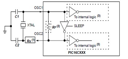
The circuit have an external clock source to dive the OSC1 Pin, series resistance Rs may be required for AT cut crystal strip. RF is the feedback resistor that’s range between 2 to 10 MΩ and buffer for the internal logic may be after or before the inverter oscillator depends upon the device.
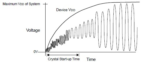
Oscillator or Resonator Start UP
The oscillator or resonator will be start up, with its oscillations when the VCC voltage of device would be increased. It’s time to start the oscillation depends upon may factors such as the layout of circuit oscillator, Quality of crystal, system temperature, value of capacitor, value of series resistor, noise of the system, VDD rise time of device, selection mode of oscillator and resonant frequency. Figure 2 shows the oscillator start up characteristics
Component Selection for Oscillator
The figure 1 shows the oscillator circuitry and according to this figure, the value of feedback Rs would be in the range between 2 to 10 MΩ. The value of this resistor varies with the deice voltages, variation in process and temperature. During the selection of resistor, the operating voltage of device and manufacturing process should be also keep in mind. For component selection also see the component specification data sheet and typical values of capacitor C1 and C2. Each device data sheet gives the specific values shown in table 1.
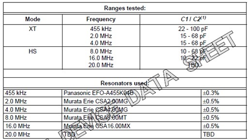
The values of capacitor C1 & C2 would be according to the above table, the high value of the capacitor increases the stability of oscillator but also increase the start-up time. The above table values are only used for design purposes but each oscillator or resonator has its own characteristics. All the resonator must have an external capacitor.
Oscillator circuit Tuning
The microchip devices have been used for many purposes such as frequency, voltage and temperature measurements. These devices must have an external crystal or capacitor for full fill the requirement of the applications. During the selection of these components following factors must be keep in yours in mind.
- The gain amplifier
- The resonant frequency
- Operational temperatures
- Oscillator start-up time
- Stability
- Life
- The power consumption
- The circuit simplification
- The use of standard components
- The combination of fewest components for desired result
- The range of supply voltages
- The desired frequency
The above factors always should be keep in mind the tuning of oscillator or resonator.
Find the Best Values for Crystal
Here we will tell, how to find the best values of crystal Clock mode, C1, C2 and Rs.Mostly the crystals are only choosing with their parallel resonant frequency but the design parameters are also important like frequency or temperature tolerance. If you want to know more about the crystal operation and ordering information, then AN 588 is the best reference for you. The internal oscillator circuit in PIC micros is basically the parallel oscillator or resonator circuit, that’s capacitance values is specified in the range between 20PF to 32 PF.
At this range the oscillator oscillates near the closest of values of desired frequency but these values may be juggle sometimes. The FOSC parameters are used for choosing the Clock mode. Clock modes are actually used, for gain selection, lower gain is used of lower frequencies and higher gain is used for higher frequencies. It is also possible to select the higher or lower gain depends upon the need of oscillator circuit. The values of C1, C2 is selected by the load capacitance, but initially the suggested values are used that is suggested by the manufacture and the table that is provided in data sheet. Ideally the capacitor values are choosing in such a way that it should be must oscillate at the highest temperature and lowest VDD.
Applications of Oscillator
- It is actually an electronics circuit that is used for producing the periodic oscillating signal that could be some time sin wave or square wave.
- It is used in signal generator for producing the oscillating signal and these signal generators are used in broadcasting devices such radio, television and transmitter.
- It is used in RF circuits for producing the RF oscillating signal.
- It is used in audio frequency devices for producing an audio frequency oscillating signal.
- The electronics amplifier is basically the linear oscillator such as transistor or op amp that is used as a feedback oscillator
- The RC oscillator circuit, which consists of resistance and capacitor is used for producing lower frequency.
- The LC oscillator circuit which consists of inductor and capacitor is used for resonant oscillating frequency signal.