
USB INTERFACING with PIC MICROCONTROLLER: The purpose of this article is to build concept about USB interface to the PIC Microcontroller. Programmer is used just first time for loading the code in microcontroller and after that we can directly load the code in microcontroller through this simpler circuit. PIC18F2550 and PIC18F4550 are famous for their USB Module.
Table of Contents
USB (Universal Serial Bus)
It is the most common connection used to connect a computer to different devices such as digital cameras, printers, scanners and external hard drives etc.
USB TRANSFER SPEEDS
USB 1.0 Supports data transfer rates of:
- 5 Mega bits per second Mbps (low speed), used for Human Input Devices e.g keyboard, mouse, joysticks etc
- 2 Mbps (high speed) used for printers, scanners etc
USB 2.0 known as hi-speed USB and capable of supporting a transfer rate up to 480Mbps.
USB 3.0 Also known as super-speed USB and supports transfer rates up to 5.0 gigabits per second (Gbps).
USB 3.1 Also known as super speed+ and capable of supporting transfer rates up to 10 Gbps.
USB Type-C Its plug connects to both “hosts and devices”.
USB PIN OUT: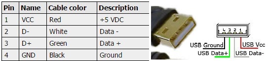
The main steps involved in this project are:
Step#1 Clock Generation
Step#2 Circuit Constructions
Step#3 Programming the Microcontroller
Step#4 Burning the code in Microcontroller
Step#5 Device Drivers
Step#6 Circuit Working
CLOCK GENERATION for USB interfacing with pic microcontroller
P18F2550/4550 supports low speed (1.5 Mb/s) and Full Speed (12 Mb/s) so for USB we have to select a specific clock. An internal clock of either 6 MHz or 48 MHz is required because of timing requirement imposed by USB.But there is a problem in using the crystal of 48MHz. This crystal is of high cost and it also creates noise. Since higher the crystal, the greater will be noise.There are numerous choices to achieve the USB module clock requirement which still provide flexibility for clocking the rest of the device from the primary oscillator source.Here, the crystal oscillator used with PIC18F4550 for USB Interfacing is 20MHz crystal oscillator. It is used for internal oscillation of the microcontroller and it is connected on 13 and 14 pin of MCU.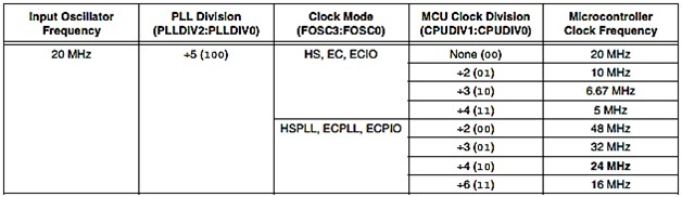
CONFIGURATION BITS SETTINGS FOR USB interfacing with pic microcontroller
In the case of 20MHz crystal:
- Set the “Oscillator Selection“ to HSPLL. It will give 20 MHz at the input of “primary oscillator”
- Set the “PLL prescaler selection” to divide by 5, so we get 4 MHz which are multiplied by 24 to get the 96 MHz for USB
- Set the “USB clock selection” to 96 MHz divided by 2
- Set the “System clock postscaler selection” to 96 divided by two.
Finally, the Oscillator frequency is set to 48 MHz. (96 MHz/2=48MHz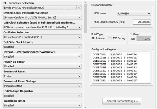
USB interfacing circuit with pic microcontroller
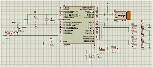
Make the circuit diagram as shown in the schematic:
- The input voltage to a PIC18F4550 Microcontroller should never exceed 5 V.
- The crystal oscillator used is 20MHZ crystal oscillator which is connected on 13 and 14 pin.
- Short 11th and 32nd pin together to 5v, similarly 12th and 31st pin to GND. But here MCU has built in connections.
- The two led’s are on RD0 and RD1 and 1 kΩ resistance is added to each LED. They are used for the communication purpose only to see that the USB communication exists.
- By this USB Interface circuit we are going to control 2 pins, RD2 and RD3.
- One switch is for the Reset button and is connected with pin 1.
- Other switch is for Bootloading connected with pin 37.
LED’s on (RD2, RD3) are used as control pins, but these control pins can be used to control other things too. It can easily interfaced with L293D Motor Driver, DC Motor, Stepper Motor, relay switches , servo etc.
Schematic on Proteus
PROGRAMMING THE PIC MICROCONTROLLER
Code for USB interfacing with microcontroller is given below. But to use this code you have to add device driver also. Before using this code, user should create USB device driver by going to tools of Mikro C for pic and click on HID terminal and generate descriptor.c file and paste this file in your main code folder.
unsigned char readbuff[64] absolute 0x500;   // Buffers should be in USB RAM, please consult datasheet
unsigned char writebuff[64] absolute 0x540;

char cnt;
char kk;

void interrupt(){
   USB_Interrupt_Proc();                   // USB servicing is done inside the interrupt
}

void main(void){
  ADCON1 |= 0x0F;                         // Configure all ports with analog function as digital
  CMCON  |= 7;                            // Disable comparators

  HID_Enable(&readbuff,&writebuff);       // Enable HID communication

  while(1){
    while(!HID_Read())
      ;

    for(cnt=0;cnt<64;cnt++)
      writebuff[cnt]=readbuff[cnt];

    while(!HID_Write(&writebuff,64))
      ;
  }
}
The code for the micro-controller is written with some special software which have own programming language similar to C e.g: mplab, microC software. The code is then compiled to a respective output. In this process the “.hex” file is generated which is to be burn/fuse in the microcontroller.
BURNING THE CODE IN MICROCONTROLLER
The output loaded into the EPROM of the microcontroller is called the firmware. We need a special hardware to fuse this output code (hex file) into the MCU. JDM programmer is an example of such device that is used to load the hex file to the MCU. It is easy to make and cheap.After loading, chip off the PIC18F4550 from the programmer (1ST time loading of hex code) and insert it back into the USB interface circuit.After this, we have to provide the driver.
We don’t have to follow this step (use of programmer) every time for loading the firmware (hex file). Once the base firmware is loaded into the chip we can update output hexfile directly with the interface development circuit with smallbootloading software.
DEVICE DRIVERS FOR USB interfacing with pic microcontroller
Connect the USB cable from the computer to the USB Interface. Even after completing the circuit and also the programming in microcontroller, it will not start working properly. As we know that new hardware installation requires driver for windows to get detected by the system.
For Driver Installation and Bootloading operation we need to download and Install USB MICROCHIP FRAMEWORK from microchip website.
CIRCUIT WORKING of USB interfacing
For starting the circuit, we have to initialize it in BOOTLOAD Mode. In the USB interface circuit, as already explained, there are two buttons,one is theRESETbutton and another is the BOOTLOAD button.
- HOLD theRESET button
- Keep the RESET pressed and then hit theBOOTLOAD button once
- Then release both buttons.
- The window will then detect the PICI8F4550 USB hardware and ask for Drivers for thisPIC18F4550 circuit/board.
- If the window is not asking for drivers then there might be some problems with the circuit.
- Suppose the Drivers for this USB device is located in
C:\MCUSB\MCUSB Driver\Debug
When the windows will ask for drivers,go for manual driver search and browse to above mention location folder for Drivers.After the Drivers are installed Led1 and Led 2 (connected on RD0 and RD1) will start to flash alternatively which means that our USB circuit is perfectly communicating with our PC.After the drivers are installed, whenever to connect this circuit with our computer, we don’t need to press reset orbootload buttonsand the LED’s will start to flash alternatively.Now the USB Interface Circuit Board is ready, and we can LOAD our own hex file into the chip Directly from USB BOARD, (without JDM programmer).
It is not necessary to use a programmer (burner circuit) for burning the firmware (hex file) into the PIC18F4550. The JDM programmer is used only for the first time programming of the code and for other stages we can use a Bootloading Software to burn new code directly from USB interface circuit to MCU. That MCU can be used for other specific circuit working for which the output code was designed for.